Two-wire transmitter

Active Publication Date: 2012-04-05
YOKOGAWA ELECTRIC CORP
View PDF9 Cites 5 Cited by
  • Summary
  • Abstract
  • Description
  • Claims
  • Application Information

AI Technical Summary

Benefits of technology

[0013]It is an illustrative aspect of the present invention to provide a two-wire transmitter which can secure a sufficient consumable power even when the output current is small and which is thus improved in performance. Also, it is another illustrative aspect of the present invention to provide a two-wire transmitter which can generate a desired circuit voltage even in the event of an abnormality.
[0015]With the above configuration, the circuit current can be controlled dynamically according to the output current. For example, when the current that is supplied from the external circuit is small (low output state), the circuit voltage can be controlled so as to be increased. This control makes it possible to relax a restriction relating to power that can be consumed in the circuit. Therefore, even in a low output state, a sufficient consumable power to, for example, increase the circuit operation speed and add new functions can be secured. Enhancement in the performance of the two-wire transmitter can thus be realized.

Problems solved by technology

However, in conventional two-wire transmitters, as described later, it is difficult to attain both of securing of more consumable power in the circuit and stabilization of circuit operation by the shunt regulator.

Method used


Image

  • Two-wire transmitter
  • Two-wire transmitter
  • Two-wire transmitter

Examples


example settings

(Example Settings)

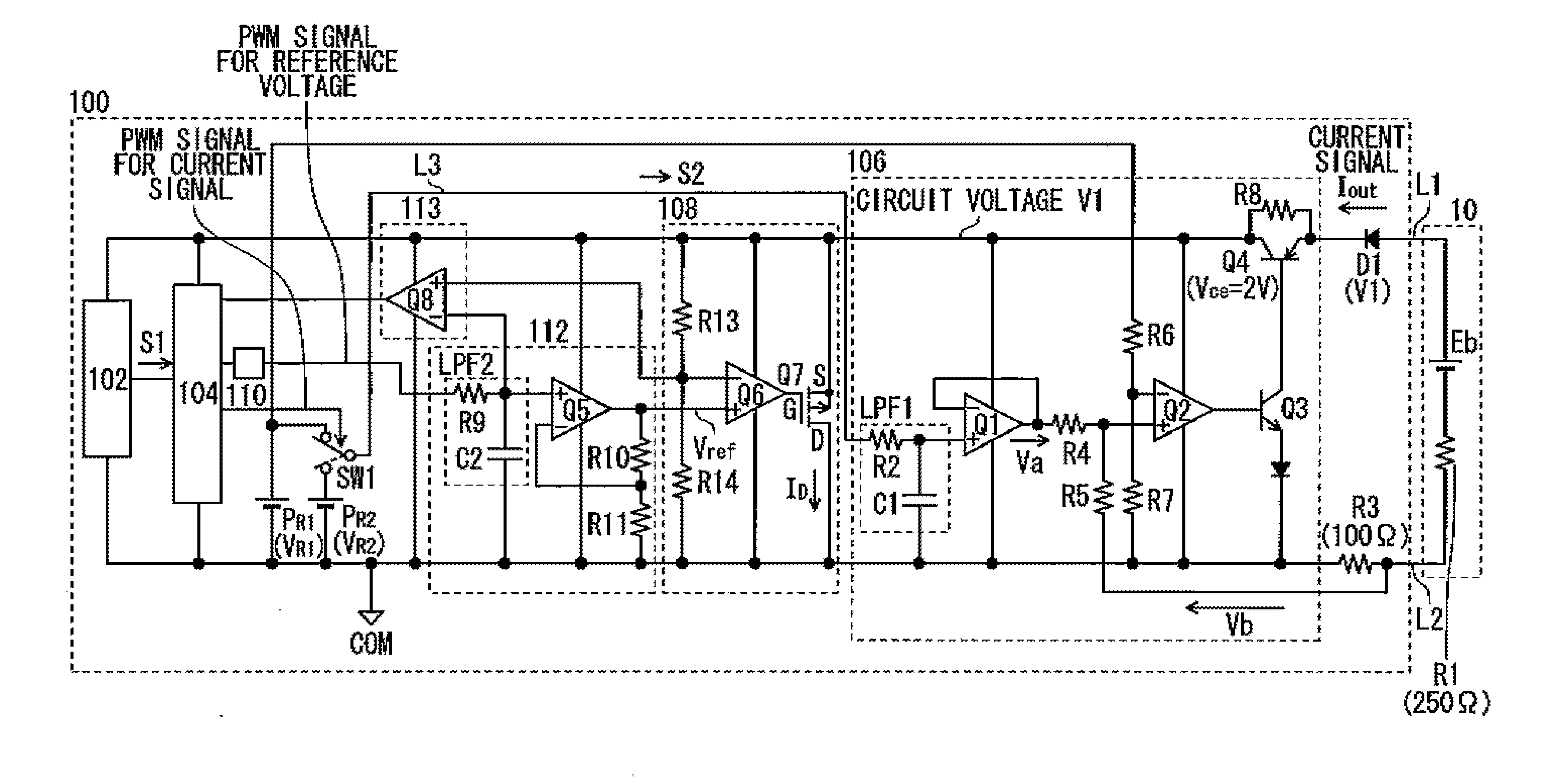
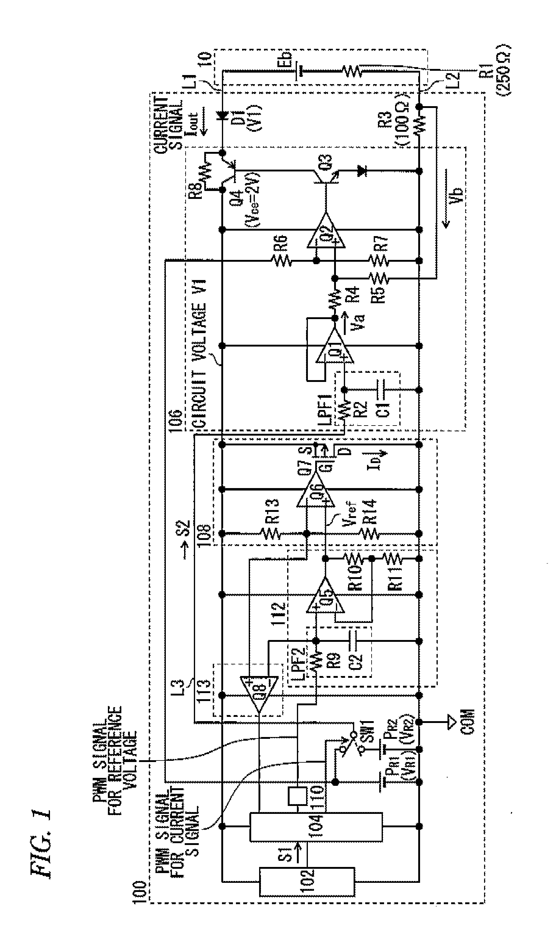
[0051]A description will be made of example settings, for realizing the consumable power of Equation (6) (46.4 mW corresponding to the output current 4 mA), of the duty ratio of the PWM signal for a reference voltage in the reference voltage output unit 110 and the gain of the error amplifier Q5 of the reference voltage processing circuit 112 in the two-wire transmitter 100. First, the reference voltage Vref for the error amplifier Q6 of the shunt regulator circuit 108 will be calculated. The reference voltage Vref is calculated by the following Equations (7) and (8). Equation (7) is a symbolized version of Equations (2) and (5) for calculating a circuit voltage V1.

V1=Eb—min−Iout(R3_max+R1_max)−A  (7)

[0052]In Equation (7), V1 is the circuit voltage, Eb—min is the minimum power voltage, Iout is the current signal, R3_max is the maximum resistance of the feedback resistor R3, R1_max is the maximum resistance of the detection resistor R1, and A is the maximum voltage ...


PUM


Abstract

There is provided a two-wire transmitter which is connected to an external circuit by two transmission lines and which outputs a certain current signal to the external circuit using the external circuit as a power source. The two-wire transmitter includes: a sensor configured to convert a physical quantity into a first electrical signal and output the first electrical signal; a signal processing circuit configured to perform certain processing on the first electrical signal and output a second electrical signal; a constant current circuit configured to determine the certain current signal to be output to the external circuit, based on the second electrical signal; a reference voltage output unit configured to output a reference voltage based on the second electrical signal; and a shunt regulator circuit configured to determine a circuit voltage of the two-wire transmitter based on the reference voltage.

Description

[0001]This application claims priority from Japanese Patent Applications No. 2010-225577, filed on Oct. 5, 2010, and No. 2011-118027, filed on May 26, 2011, the entire contents of which are herein incorporated by reference.BACKGROUND[0002]1. Technical Field[0003]The present invention relates to a two-wire transmitter which is connected to an external circuit by two transmission lines and which outputs a prescribed current signal to the external circuit while using the external circuit as a power source.[0004]2. Related Art[0005]A two-wire transmitter is a device which is connected to an external circuit by two transmission lines and which converts prescribed information (a physical quantity) acquired from a sensor or the like into a current signal and outputs the current signal to the external circuit while using the external circuit as a power source. Two-wire transmitters are used widely as field devices such as a differential pressure / pressure transmitter and a temperature transm...

Claims


Application Information

Patent Timeline
IPC IPC(8): H03K7/08H04L25/00
CPCG08C19/02
Inventor IWANO, YOUICHIISHIKAWA, IKUHIKOHAGIWARA, RYOUENDO, KAZUYUKI
Owner YOKOGAWA ELECTRIC CORP
Why Eureka
Try Eureka