
Continuous transmit focusing method and apparatus for ultrasound imaging system

a transmit beam and ultrasound imaging technology, applied in tomography, instruments, using reradiation, etc., can solve the problems of limited transmit beam depth, lateral image non-uniformity, and potential frame rate, so as to improve performance/frame rate tradeoff, improve transmit resolution, and reduce round-trip sidelobe clutter

Active Publication Date: 2012-04-05
SHENZHEN MINDRAY BIO MEDICAL ELECTRONICS CO LTD
View PDF4 Cites 26 Cited by
  • Summary
  • Abstract
  • Description
  • Claims
  • Application Information

AI Technical Summary

Benefits of technology

This approach enhances the acoustic acquisition rate, improves lateral resolution, and maintains continuous transmit focus throughout the region of interest, resulting in higher frame rates and reduced power consumption, especially beneficial for battery-powered ultrasound systems.

Problems solved by technology

This leads to lateral image non-uniformity, which is undesirable for high quality ultrasound imaging.
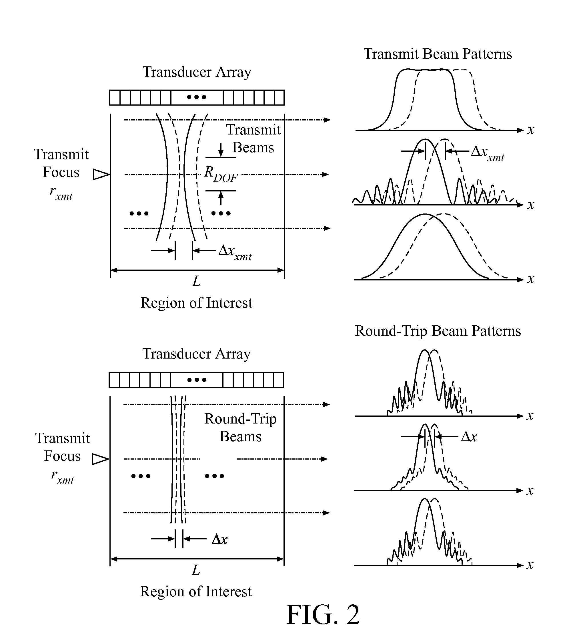
If the transmit and receive F-numbers are made equal, i.e., Fxmt=Frcv=1.0, then the reduction in potential frame rate using (4) is ˜1.4, which is not as dramatic as when the receive F-number is much lower than the transmit F-number; however, an additional problem is introduced, namely the limited depth of field of the transmit beam.
This introduces image lateral non-uniformity and higher clutter away from the transmit focus and is undesirable in high quality ultrasound images.
This produces a significant loss in acoustic acquisition rate due to the multiple transmit firings along the same line.

Method used


Image

  • Continuous transmit focusing method and apparatus for ultrasound imaging system
  • Continuous transmit focusing method and apparatus for ultrasound imaging system
  • Continuous transmit focusing method and apparatus for ultrasound imaging system

Examples


example

Planar 1-D Transducer, Linear Scan Format, 2-D Image Formation

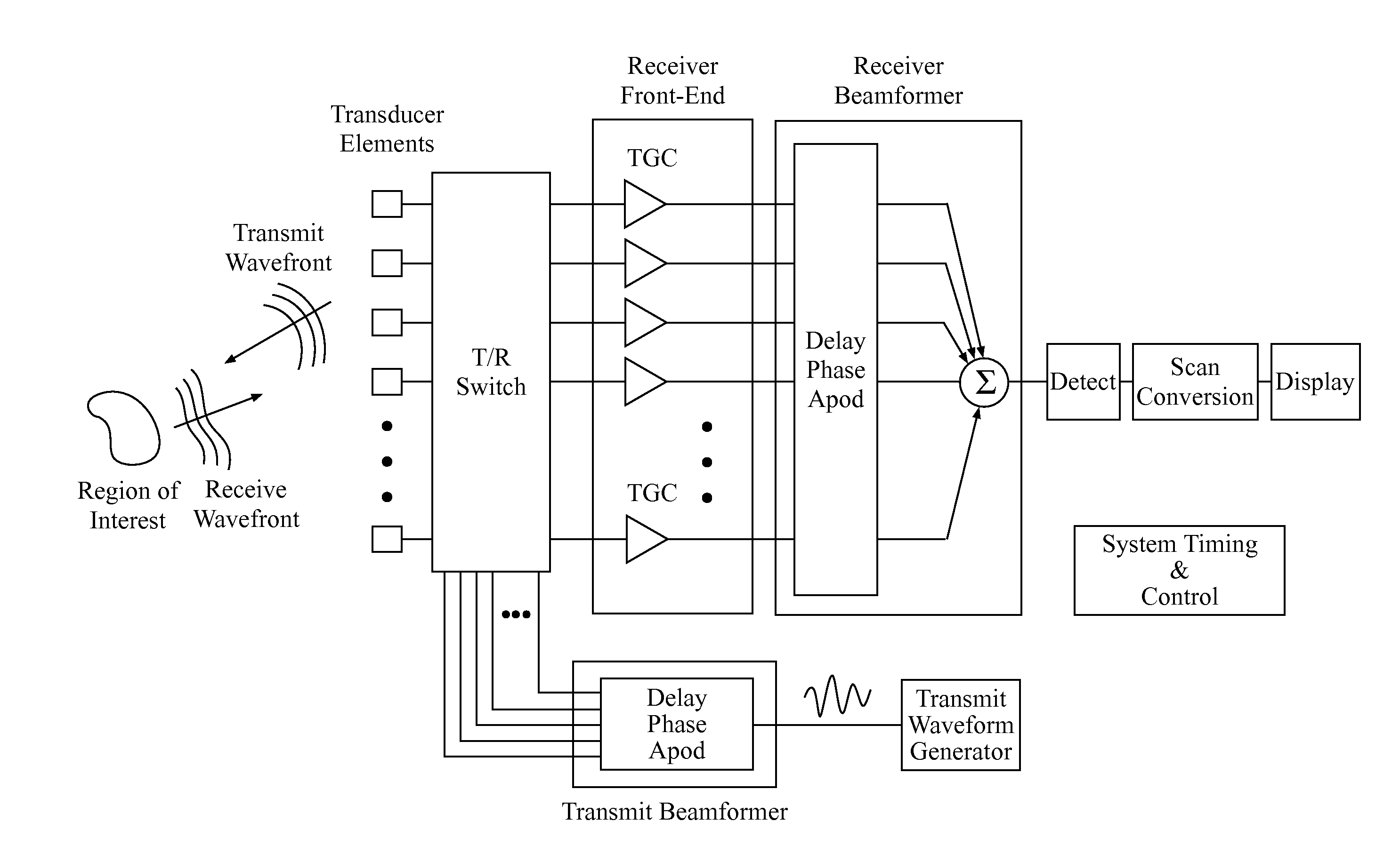
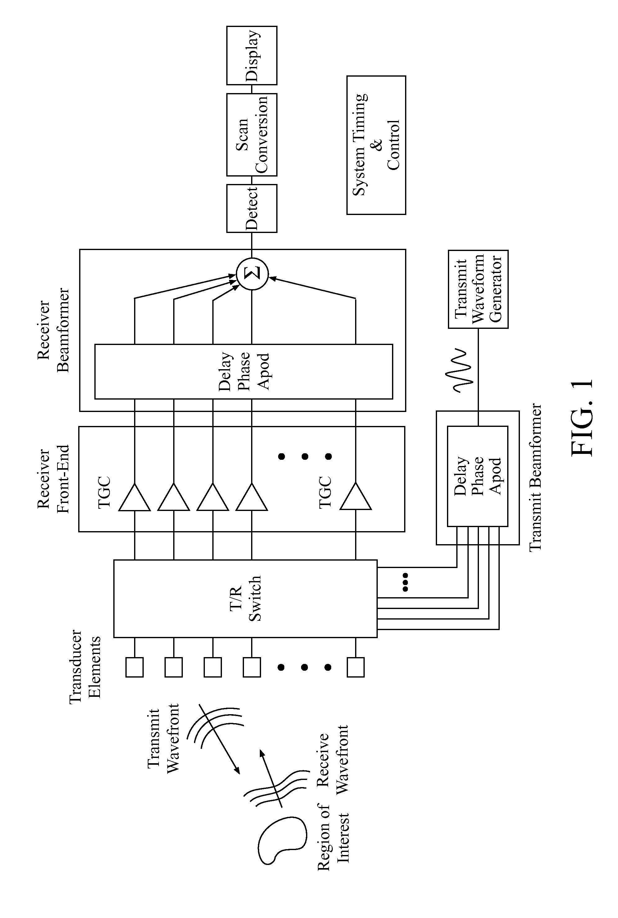
[0060]Consider the demodulated receive signal from a given transducer element as shown in FIG. 6. The signal {tilde over (s)}ch received by a transducer element located at r′=x′p, from a point scatterer at r=(r, x), insonified by the n-th transmit beam wavefront {tilde over (s)}xmt(t−Txmt, x−xn, r, rxmt), due to a transmit excitation of sxmt(t), where xn is the transmit beam origin location on the array, can be mathematically expressed as given by (15). The receive signal sch is simply the backscattered signal from the point scatterer at (r, x), attenuated and delayed by the propagation time Trcv from (r, x) back to the transducer receive element at x′p.

Txmt=Txmt(x-xn,r,rxmt)=rc+ΔTxmt(x-xn,r,rxmt)Trcv=Trcv(xp′-x,r)=r2+(xp′-x)2cs~ch(t-Txmt-Trcv,xp′,x-xn,r,rxmt)=-jϕd(t)∫hrcv(t-t′,xp′)s~xmt(t′-Txmt-Trcv,x-xn,r,rxmt)t′(15)

[0061]If the transmit excitation by the transducer is represented by

sxmt(t)=p(t)ejωxt  (16)

where p(t) is ...


PUM


Abstract

In one embodiment, an ultrasound imaging method comprises: providing a probe that includes one or more transducer elements for transmitting and receiving ultrasound waves; generating a sequence of spatially distinct transmit beams which differ in one or more of origin and angle; determining a transmit beam spacing substantially based upon a combination of actual and desired transmit beam characteristics, thereby achieving a faster echo acquisition rate compared to a transmit beam spacing based upon round-trip transmit-receive beam sampling requirements; storing coherent receive echo data, from two or more transmit beams of the spatially distinct transmit beams; combining coherent receive echo data from at least two or more transmit beams to achieve a substantially spatially invariant synthesized transmit focus at each echo location; and combining coherent receive echo data from each transmit firing to achieve dynamic receive focusing at each echo location.

Description

CROSS-REFERENCES TO RELΔTED APPLICΔTIONS[0001]This application is a continuation of U.S. patent application Ser. No. 11 / 492,471, entitled “Continuous Transmit Focusing Method and Apparatus For Ultrasound Imaging System”, filed on Jul. 24, 2006, which claims priority to provisional patent application No. 60 / 701,812, filed Jul. 22, 2005, the entire disclosures of which are incorporated herein by reference in their entirety for all purposes.BACKGROUND OF THE INVENTION[0002]This invention relates generally to ultrasound imaging systems and, more particularly, to continuous transmit focusing for ultrasound imaging systems.[0003]Conventional ultrasound imaging systems generally form an image in the following manner. A short acoustic pulse is transmitted into a region of interest from a subset of transducer elements on an array, focused at a particular depth and direction. The acoustic wavefront formed by the superposition of the transmitted pulses propagates along the selected direction a...

Claims


Application Information

Patent Timeline
Patent Type & Authority Applications(United States)
IPC IPC(8): A61B8/14
CPCG01S7/52019G01S7/52046G01S7/52095G01S15/8927G01S15/8993G10K11/341A61B8/4483A61B8/145A61B8/4461A61B8/4488A61B8/4494A61B8/463A61B8/5246G01S15/8915
Inventor NAPOLITANO, DAVID J.DEBUSSCHERE, BRIAN DEREKMCLAUGHLIN, GLEN W.MO, LARRY Y.L.CHOU, CHING-HUAJI, TING-LANSTEINS, ROBERT W.
Owner SHENZHEN MINDRAY BIO MEDICAL ELECTRONICS CO LTD
Learn More