Positionable Valvuloplasty Catheter

a valvuloplasty and catheter technology, applied in the field of balloon catheters, can solve the problems of patient death, inability to accurately place the valvuloplasty catheter, and inability to accurately guide the fluoroscopic guidance, so as to improve the locking of the balloon, improve the dp/dv curve, and reduce the diametric magnitude of the dilation

Active Publication Date: 2012-04-05
INTERVALVE MEDICAL INC
View PDF12 Cites 28 Cited by
  • Summary
  • Abstract
  • Description
  • Claims
  • Application Information

AI Technical Summary

Benefits of technology

[0011]Further inflation of the balloon from 0.5 atm to higher than 2 atm causes the sc portion of the balloon to further dilate the leaflets outward. The stenotic leaflets can come into contact with the aortic sinus; this contact will be noted by an inflection point and an increase in the slope of the dP / dV curve. Observation of the slope of the dP / dV compliance curve following contact of the leaflets with the sinus reflects the compliance of the stenotic leaflets, the sinus, and the sc portion of the balloon. Subtraction of the balloon compliance allows the physician to assess the compliance of the aortic tissues and determine if further dilation is warranted. This subtraction can be accomplished automatically with the computer control system and the tissue compliance can be displayed on a monitor.
[0012]The balloon structure in one preferred embodiment can have a dogbone shape in its fully expanded conformation. The dogbone shape can provide an improved locking of the balloon on each side, upstream and downstream, of the annulus. Also, the dogbone shape can allow the stenotic leaflets to be dilated in a hyperextended manner while maintaining a lower dilation diametric magnitude for the annulus.

Problems solved by technology

Movement of the heart, flow of blood, and inaccuracies in of fluoroscopic guidance do not always allow for accurate placement of the valvuloplasty catheter across the aortic annulus and sinus.
Dilation of the aortic valve leaflets into the aortic sinus can cause the sinus to become overly distended and potentially encounter dissection or tearing which can result in patient death.
Under current fluoroscopic visualization the physician does not know when the balloon has made contact with the leaflets, does not know if the aortic sinus is being overdistended, and he does not have information indicating the compliance characteristics of the aortic sinus or annulus.

Method used


Image

  • Positionable Valvuloplasty Catheter
  • Positionable Valvuloplasty Catheter
  • Positionable Valvuloplasty Catheter

Examples


Embodiment Construction

[0024]Specific embodiments of the invention will now be described with reference to the accompanying drawings. This invention may, however, be embodied in many different forms and should not be construed as limited to the embodiments set forth herein; rather, these embodiments are provided so that this disclosure will be thorough and complete, and will fully convey the scope of the invention to those skilled in the art. The terminology used in the detailed description of the embodiments illustrated in the accompanying drawings is not intended to be limiting of the invention. In the drawings, like numbers refer to like elements.

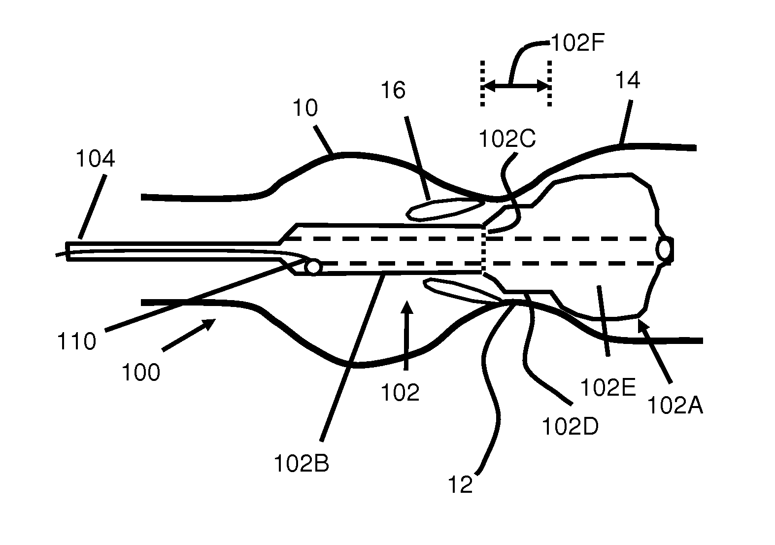
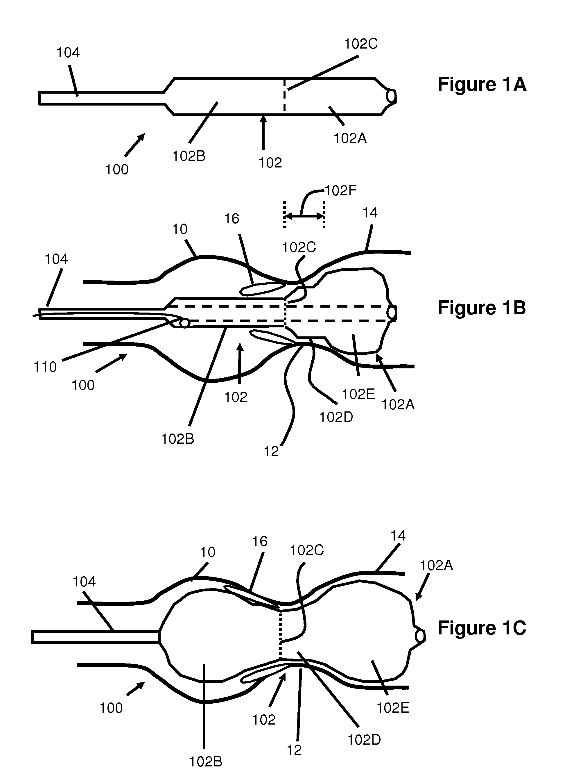
[0025]The present invention includes a balloon dilatation catheter for positioning within a tubular vessel of the body and dilating a stenotic portion of the vessel. When used for valvuloplasty, the distal region or portion of the balloon is positioned in the left ventricular outflow tract and is inflated first to help position the balloon to a desirable locat...


PUM


Abstract

In one embodiment, a balloon catheter is provided for use during annuloplasty. Preferably, the balloon includes a distal, noncompliant portion and a proximal semi-compliant portion which allows for sequential inflation, reliable positioning, and compliance measurement.

Description

RELATED APPLICATIONS[0001]This application claims priority to U.S. Provisional Application Ser. No. 61 / 382,446 filed Sep. 13, 2010 entitled Positionable Valvuloplasty Catheter, which is hereby incorporated herein by reference.BACKGROUND OF THE INVENTION[0002]The following patents are hereby incorporated by reference in their entirety: U.S. Pat. Nos. 7,618,432; 7,744,620; and 7,951,111.[0003]This invention is related to balloon catheters used for locating a position within a blood vessel or tubular member of the body, dilating tissue found within the tubular member, and measuring the compliance characteristics of tissue or the tubular member. Specifically, this device is intended for locating the balloon across the aortic annulus and aortic sinus, dilating the diseased aortic valve leaflets, and measuring the compliance characteristics of the annulus or sinus region.[0004]Currently cylindrically shaped balloons are used to perform valvuloplasty procedures wherein the stenotic aortic ...

Claims


Application Information

Patent Timeline
Patent Type & Authority Applications(United States)
IPC IPC(8): A61B17/22A61F2/958
CPCA61M25/1002A61M29/02A61M25/104A61M2025/1084A61M2025/1072A61M2025/1059
Inventor DRASLER, WILLIAMPEDERSEN, WESLEYUNGS, MARK
Owner INTERVALVE MEDICAL INC
Why Eureka
Try Eureka