Equipment operation state measurement device, equipment operation state measurement method, and control program

a technology of operation state and measurement device, which is applied in the direction of programme control, instruments, total factory control, etc., can solve the problems of equipment not being able to determine whether to improve the operating rate and productivity of equipment, stop the equipment, and cannot specify whether to improve the equipment's operation state, etc., to achieve the effect of reducing costs and improving equipment productivity

Inactive Publication Date: 2012-04-05
ORMON CORP
View PDF5 Cites 24 Cited by
  • Summary
  • Abstract
  • Description
  • Claims
  • Application Information

AI Technical Summary

Benefits of technology

[0046]As described above, the present invention can set information regarding a detailed operation state for each operation state of equipment. Based on the information, a user can, for example, analyze a processing object, stop cause, or the like that generates waste, and thus can take measures to improve productivity of the equipment. In addition, when there is an operation state for which a detailed operation state is not set, the present invention issues an alert to prompt an input of the detailed operation state information. Thus, an operator can input information regarding a detailed operation state into the equipment operation state measurer before forgetting the detailed operation state of the operation state, thereby making it possible to keep accurate records on the operation states of the equipment.
[0047]Moreover, in application of the present invention, it is not necessary to modify a ladder program of a PLC that controls equipment. Therefore, it is possible to introduce the equipment operation state measurer of the present invention with reduced costs, as compared with a device that measures an operation state of equipment using a PLC.
[0048]Other objects, characteristics, and advantages of the present invention will be fully understood from the description hereinafter. Further, merits of the present invention will be evident from the following descriptions with reference to the accompanying drawings.

Problems solved by technology

Therefore, it is unable to specify whether a cause that has stopped the equipment is due to a breakdown of the equipment, set-up (change of processing objects, jigs, or the like) due to a process change, or a replacement of consumable parts (cutting tools or the like).
Thus, major stop causes of the equipment cannot be determined to improve an operating rate and productivity of the equipment.
Therefore, it is impossible to take measures to reduce stopped states, which are considered wasteful.
Even when equipment is in a stopped state, however, it consumes some power.
In other words, the equipment consumes power that associates with stopped states, such as stand-by power and the like.
Since the PLCs cannot provide information on power consumption of equipment, the equipment operation state measurers in Patent Literatures 2 to 4 cannot acquire information regarding electric energy consumed by the equipment with respect to each stop cause.
Therefore, it is difficult to investigate wasted electric energy consumption in the equipment in order to reduce power consumption of, for example, a factory, based on the information acquired from the equipment operation state measurers.

Method used


Image

  • Equipment operation state measurement device, equipment operation state measurement method, and control program
  • Equipment operation state measurement device, equipment operation state measurement method, and control program
  • Equipment operation state measurement device, equipment operation state measurement method, and control program

Examples


first embodiment

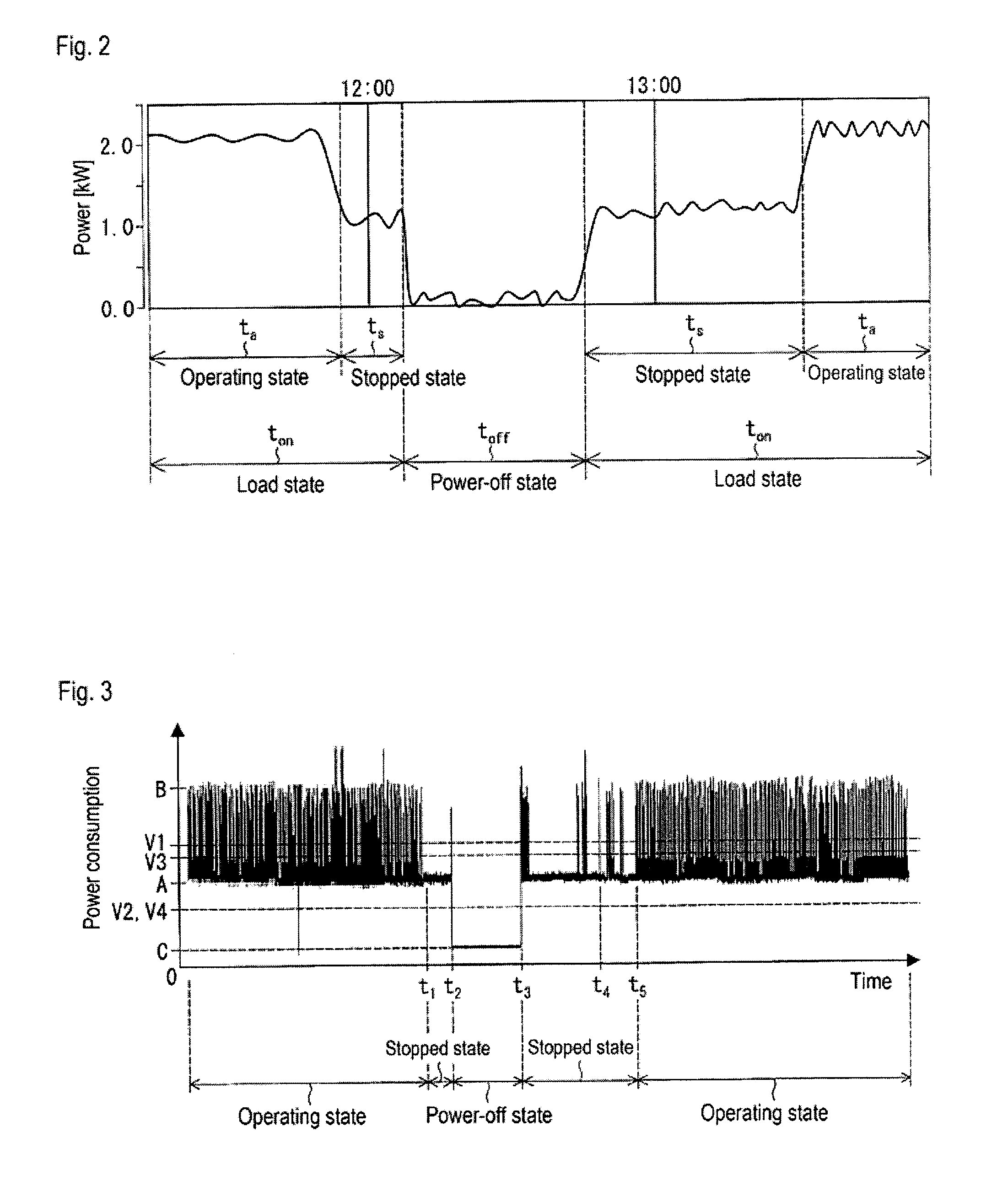
[0073]Hereinafter, an embodiment of the present invention is described in detail with reference to the drawings. Prior to the description of the present embodiment, states of object equipment are described with reference to FIG. 2.

[0074]FIG. 2 is a chart illustrating an operational status of a press machine. Specifically, FIG. 2 is a graph illustrating temporal fluctuation in power (kW) consumed by the press machine. FIG. 2 shows a graph of data for several hours. A press machine is used as an example of the object equipment in FIG. 2, however the same is applicable to other types of object equipment.

[0075]In the graph of FIG. 2, time toff, in which power consumption is close to 0 kW, is a period when the press machine is powered off. This state is referred to as a power-off state. On the other hand, time ton, which is a period other than the time toff in the power-off state, is a period when the press machine is powered on. This state is referred to as a load state.

[0076]Within a l...

second embodiment

[0122]In the configuration of the first embodiment, a stop cause and the like is determined for each stopped state based on an input of the stop cause and the like by an operator to the cause inputter. However, the equipment operation state measurer may determine a stop cause and the like based on information input from an external sensor. In the present embodiment, descriptions are provided for a configuration that employs a temperature sensor as the above sensor to acquire temperature information (state information) of an object piece of equipment and to determine a stop cause. As a matter of convenience in description, only points different from the first embodiment are described hereinafter.

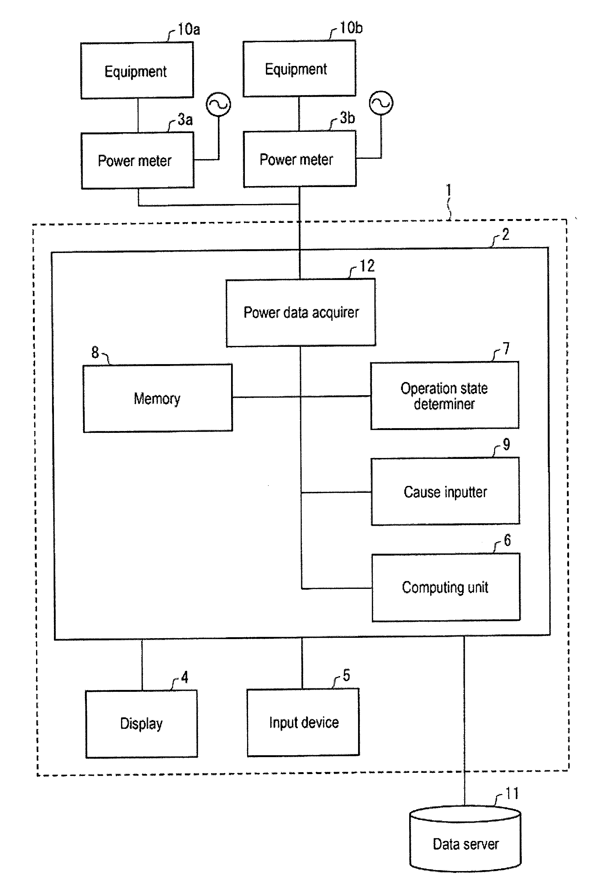
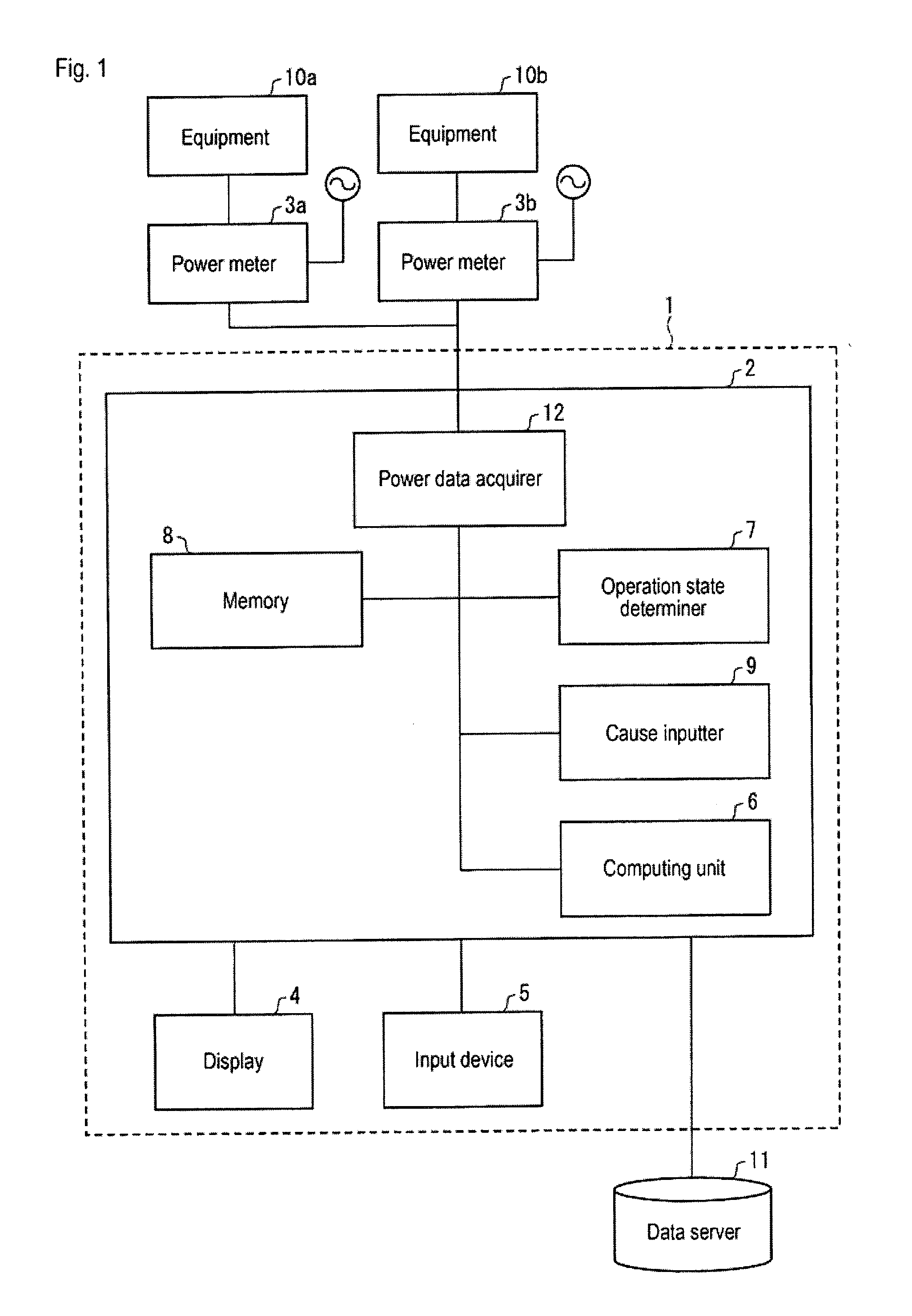
[0123]FIG. 7 is a block diagram showing a configuration of an equipment operation state measurer 16 according to the present embodiment. The calculator 2 of the equipment operation state measurer 16 includes a temperature data acquirer (state information acquirer) 13 and a cause determiner (d...

third embodiment

[0129]In the present embodiment, descriptions are provided for a configuration that acquires vibration information (state information) of an object piece of equipment using a vibration sensor and determines a stop cause. As a matter of convenience in description, only points different from the first embodiment are described hereinafter.

[0130]FIG. 9 is a block diagram illustrating a configuration of an equipment operation state measurer 17 according to the present embodiment. The calculator 2 of the equipment operation state measurer 17 includes a vibration data acquirer (state information acquirer) 18 and a cause determiner (detailed operation state determiner) 19. A vibration sensor 20 measures vibration of the equipment 10a.

[0131]The vibration data acquirer 18 acquires, from the vibration sensor 20, vibration information of the equipment 10a as state information of the equipment 10a. The cause determiner 19 determines a stop cause of the equipment 10a based on the acquired vibrat...


PUM


Abstract

The invention is directed towards an equipment operation state measurer having a power data acquirer and an operation state determiner. The power date acquirer acquires power consumption of equipment changing according to an operation state of the equipment. Additionally, a cause inputter accepts an input of a stop cause of the equipment from an operator, with respect to a stopped state determined by the operation state determiner, and sets the stop cause of the stopped state based on the input. Also, a computing unit obtains electric energy consumption for each stop cause, by integrating a period during which the stopped state corresponding to the stop cause continues and the power consumption in the period during which the stopped state continues, and is capable of measuring duration of the stopped state and the electric energy consumption for each stop cause of the equipment.

Description

CROSS-REFERENCE TO RELATED APPLICATIONS[0001]This is a continuation application of PCT / JP2010 / 056220 filed Apr. 6, 2010, designating the United States of America, the disclosure of which, including the specification, drawings, and claims, is expressly incorporated by reference in its entirety. The disclosures of Japanese Patent Application No. 2009 / 096322, filed on Apr. 10, 2009 and Japanese Patent Application No. 2010 / 050429, filed on Mar. 8, 2010, including the specification, drawings, and claims is expressly incorporated by reference in their entiretiesTECHNICAL FIELD[0002]The present invention relates to an equipment operation state measurer (or measurement device) that measures outage duration of equipment for each stop cause of the equipment that executes various processes in production lines, and an equipment operation state measurement method.BACKGROUND TECHNOLOGY[0003]In order to improve productivity in production lines of factories and the like, it is essential to know an ...

Claims


Application Information

Patent Timeline
Patent Type & Authority Applications(United States)
IPC IPC(8): G06F19/00G01R21/00
CPCG05B19/4184G06Q50/00G05B2219/37348G05B2219/32021Y02P70/10Y02P90/02
Inventor SAITO, HIROSHIENDO, MAKI
Owner ORMON CORP
Why Eureka
Try Eureka