Method and arrangement for blind demultiplexing a polarisation diversity multiplex signal

a multi-segment, blind demultiplexing technology, applied in the direction of coding, code conversion, fault response, etc., can solve the problems of complex adaptive optical polarisation controller, complex polarisation control, and inability to manually align the polarisation of transmitter and receiver for fiber links

Active Publication Date: 2012-04-05
XIEON NETWORKS SARL
View PDF9 Cites 18 Cited by
  • Summary
  • Abstract
  • Description
  • Claims
  • Application Information

AI Technical Summary

Benefits of technology

[0020]the control unit calculating error correction values by multiplying the error correction factor by an update factor and by an associated x- or y-polarisation sample, and calculating corrected filter coefficients by adding the correction values to the filter coefficients determining corrected transfer functions.

Problems solved by technology

Manually aligning the transmitter and receiver polarisations is not possible for fiber links with time-varying polarisation changes.
In fiber optic systems, polarisation changes arbitrarily with time and an adaptive optical polarisation controller is complicated and expensive.
Moreover, PDL (polarisation depending loss) leads to a polarisation-dependent attenuation, thereby causing different SNR-levels (signal-to-noise ratio) for the two polarisations.
Since coherent reception also enables the separation of orthogonally polarized signals in the electrical domain, the use of a similar polarisation controller is not needed nor economically viable.
Current fiber network standards do not incorporate training sequences, so that in the receiver the channel has to be estimated blindly without any further knowledge.
Applying these equalisation algorithms can lead to degenerative solutions, where one polarized signal is demultiplexed to both output polarisations and half of the information lost.

Method used


Image

  • Method and arrangement for blind demultiplexing a polarisation diversity multiplex signal
  • Method and arrangement for blind demultiplexing a polarisation diversity multiplex signal
  • Method and arrangement for blind demultiplexing a polarisation diversity multiplex signal

Examples


Embodiment Construction

[0027]An embodiment of the invention will be described as a part of a coherent polarisation diversity multiplex (polmux) receiver. This system transmits two optical signals SH and SV with the same carrier wavelength but orthogonal polarisations in two subchannels of a single-carrier transmission channel.

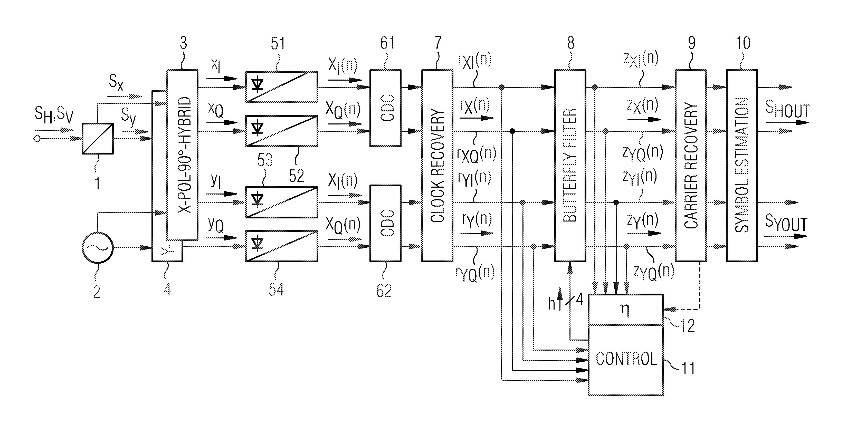
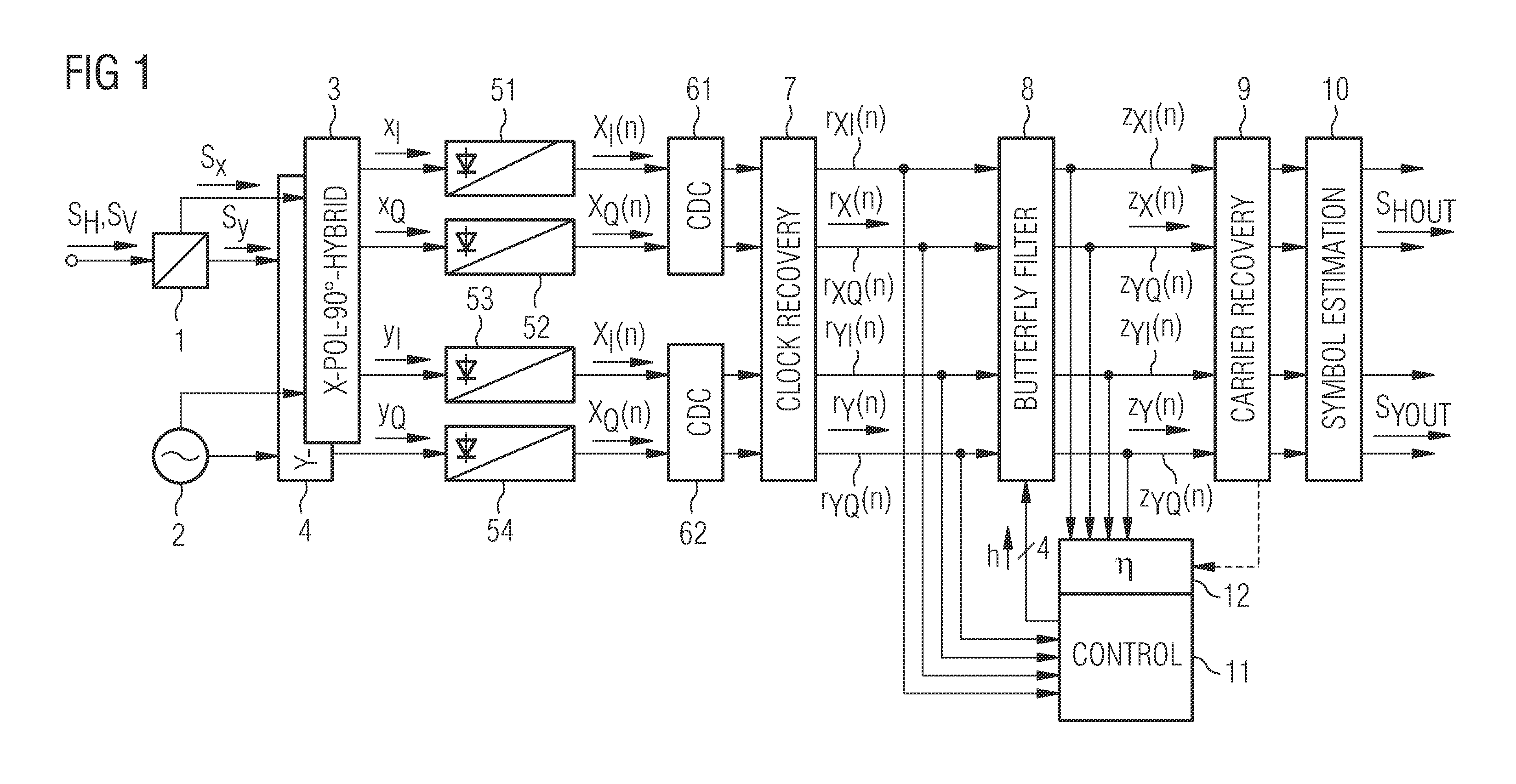
[0028]FIG. 1 shows a schematic block diagram of a today's polarisation multiplex receiver. The received polmux (polarisation diversity multiplex) signal SH, SV is split by a polarisation beam splitter 1 into an x-component signal SX with x-polarisation and an orthogonal y-component signal SY with y-polarisation. A local oscillator 2 generates a constant wave signal, which is split into two orthogonally polarized constant wave signals and fed together with the orthogonal component signals Sx and Sy to two 90° hybrids 3 and 4, where each x- and y-component signal is split into two orthogonal components xI, xQ and yI, yQ respectively (in-phase component I, quadrature component Q or real...


PUM


Abstract

A received optical signal (SH, Sv) is coherently demodulated and converted into orthogonal x-polarisation samples (rx(n)), and y-polarisation samples (ry(n)). These samples are converted into signal x-samples zx(n) and signal y-samples zy(n) by an FIR butterfly filter (8). Correction values are calculated in an error calculating circuit (12) of a control unit (11) and added to filter transfer functions derived by a standard algorithm to determine corrected filter coefficients. Degenerate convergences calculating the transfer functions are avoided.

Description

FIELD OF THE INVENTION[0001]The invention refers to a method and an arrangement for blind demultiplexing of polarisation diversity signals for a coherent receiver.BACKGROUND OF THE INVENTION[0002]In order to meet the growing demand for internet bandwidth with traffic growth rates around 40-50% per year, telecommunication component providers face the task of increasing the spectral efficiency of fiber utilization. After 10 Gbit / s systems (G—Giga) became successful in the 1990's, solutions for 40 Gbit / s became available in the last years. Standardization and research are now focused on the development of 100 Gbit / s systems with coherent polarisation multiplexed (CP) QPSK being the most likely modulation format for next generation systems. Since polarisation multiplexing utilizes both light polarisations, it is possible to send the signal at a rate of ˜25-28 Gsymbols per second, thus fitting nicely into the standard 50 GHz grid for DWDM (Dense Wavelength Diversity Multiplex) optical sy...

Claims


Application Information

Patent Timeline
Patent Type & Authority Applications(United States)
IPC IPC(8): H03M13/05G06F11/10
CPCH04J14/06H04L27/223H04L25/0238
Inventor KUSCHNEROV, MAXIMLANKL, BERTHOLDSPINNLER, BERNHARD
Owner XIEON NETWORKS SARL
Why Eureka
Try Eureka