Steering Device
a steering device and steering wheel technology, applied in the direction of steering parts, vehicle components, transportation and packaging, etc., can solve the problems of increasing manufacturing costs, difficult assembly operation, and degrading the operational ability of telescopic operation, so as to facilitate assembly work, reduce manufacturing costs, and reduce man-hours
- Summary
- Abstract
- Description
- Claims
- Application Information
AI Technical Summary
Benefits of technology
Problems solved by technology
Method used
Image
Examples
first embodiment
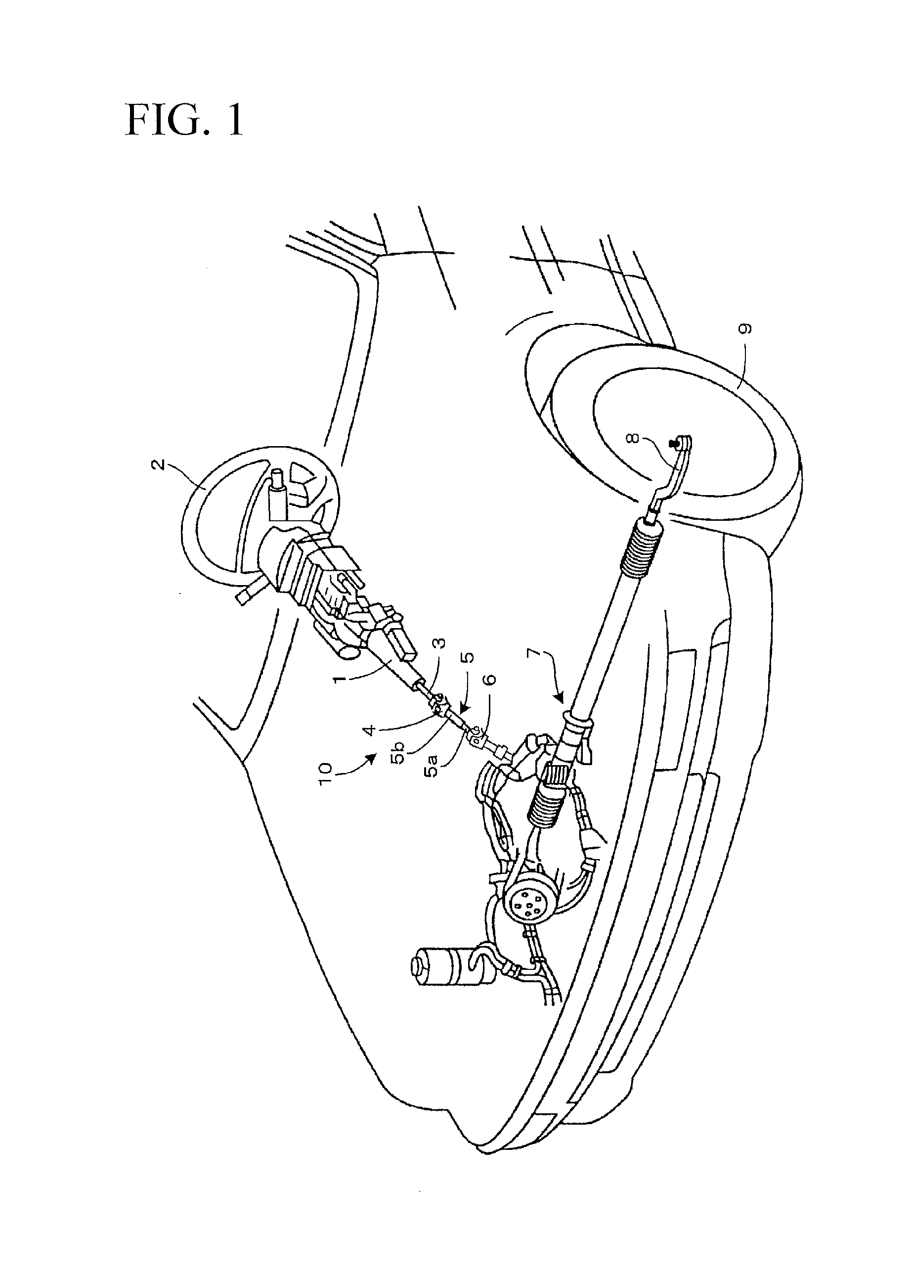
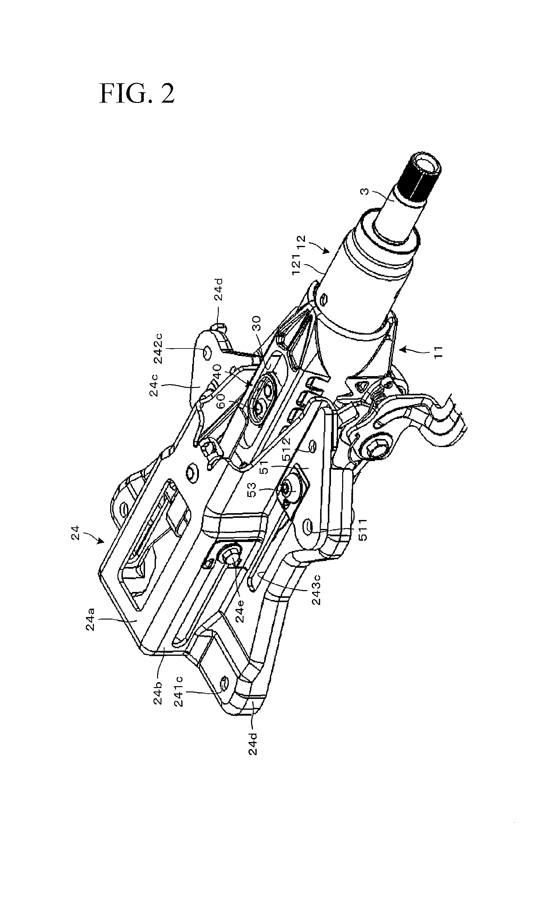
[0036]FIG. 1 is an overall perspective view showing a steering device 10 according to the invention mounted on a vehicle. As shown in FIG. 1, a hollow and cylindrical column 1 is mounted on a vehicle body. The column 1 rotatably supports a steering shaft 3. A steering wheel 2 is attached to the right end (to the rear of the vehicle body) of the steering shaft 3. An intermediate shaft 5 is coupled to the left end (to the front of the vehicle body) of the steering shaft 3 via a universal joint 4.
[0037]The intermediate shaft 5 includes a solid intermediate inner shaft 5a formed with a male spline and a hollow and cylindrical intermediate outer shaft 5b formed with a female spline. The male spline of the intermediate inner shaft 5a telescopically (slidably) engages with the female spline of the intermediate outer shaft 5b so as to be able to transmit the rotation torque.
[0038]To the rear of the vehicle body, the intermediate outer shaft 5b is coupled to the universal joint 4. To the fro...
second embodiment
[0078]The second embodiment of the invention will be described. FIG. 13 shows a stopper according to the second embodiment of the invention. FIG. 13 (1) is equivalent to FIG. 7 (1) of the first embodiment. FIG. 13 (2) is a sectional view taken along the line F-F in FIG. 13 (1). FIG. 13 (3) is a sectional view taken along the line G-G in FIG. 13 (2). The following description contains only differences from the first embodiment and omits the duplication. The same parts are depicted by the same reference numerals.
[0079]The second embodiment shows an example of fixing the stopper using one pop rivet. According to the second embodiment as shown in FIG. 13, the long hole 30 is formed in the outer column 11 as long as a telescopic positioning range in the axial direction similarly to the first embodiment.
[0080]Similarly to the first embodiment, a stopper 401 according to the second embodiment includes the oval side plate 41 as a plan view and the bottom plate 42 for covering the bottom fac...
third embodiment
[0083]The third embodiment of the invention will be described. FIG. 14 shows a stopper according to the third embodiment of the invention. FIG. 14 (1) is equivalent to FIG. 7 (1) of the first embodiment. FIG. 14 (2) is a sectional view taken along the line H-H in FIG. 14 (1). FIG. 14 (3) is a sectional view taken along the line J-J in FIG. 14 (2). The following description contains only differences from the above-mentioned embodiments and omits the duplication. The same parts are depicted by the same reference numerals.
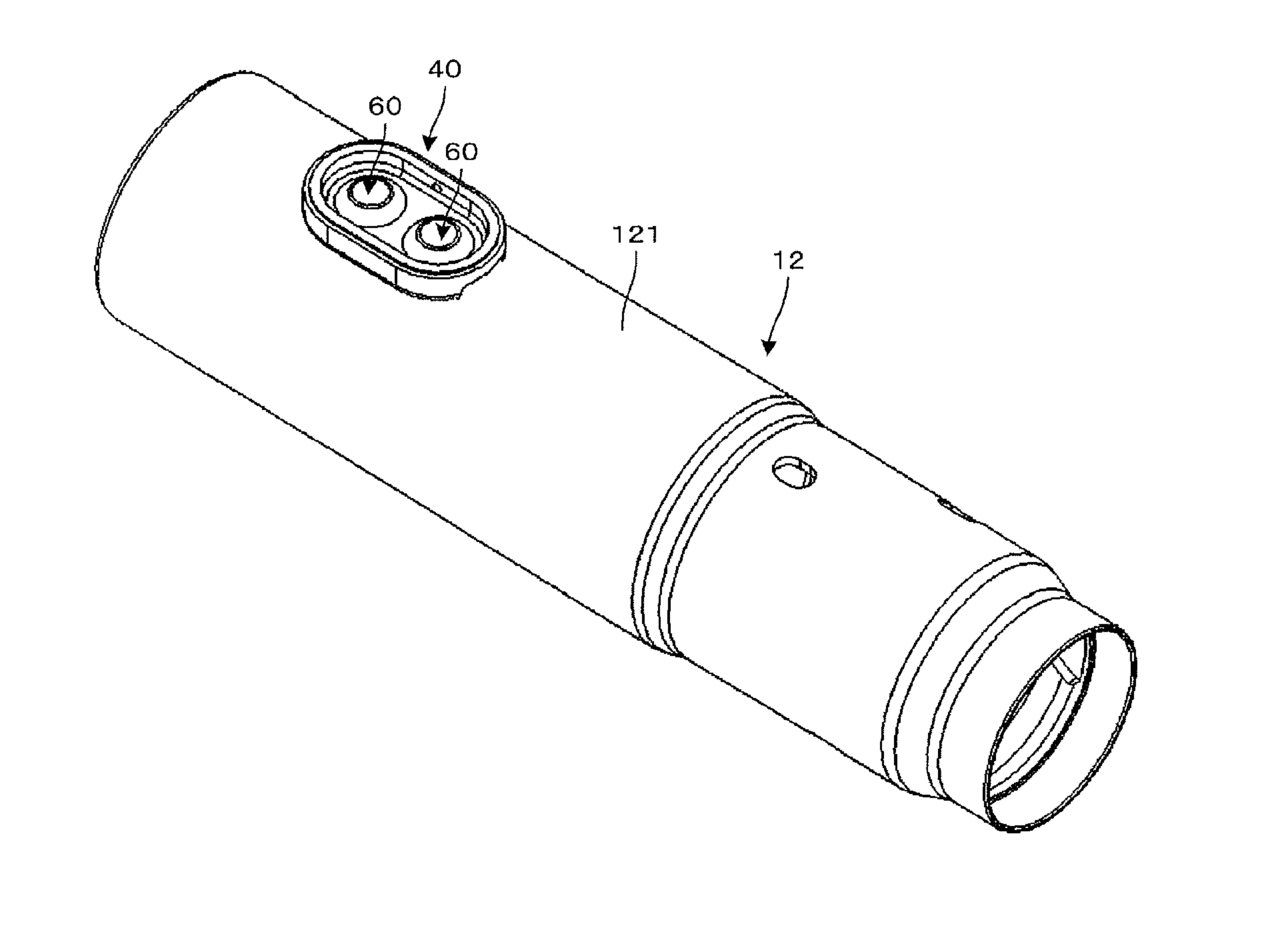
[0084]The third embodiment provides an example of omitting the stopper and using one pop rivet as the stopper. According to the third embodiment as shown in FIG. 14, the long hole 30 is formed in the outer column 11 as long as a telescopic positioning range in the axial direction similarly to the first embodiment. The one first through-hole 123 is formed in the inner column 12. The one pop rivet 60 is inserted into the first through-hole 123 from the outer curved surf...
PUM
 Abstract
Description
Claims
Application Information
 - R&D
- Intellectual Property
- Life Sciences
- Materials
- Tech Scout
- Unparalleled Data Quality
- Higher Quality Content
- 60% Fewer Hallucinations
Browse by: Latest US Patents, China's latest patents, Technical Efficacy Thesaurus, Application Domain, Technology Topic, Popular Technical Reports.
© 2025 PatSnap. All rights reserved.Legal|Privacy policy|Modern Slavery Act Transparency Statement|Sitemap|About US| Contact US: help@patsnap.com


