Vehicle cooling system

a cooling system and vehicle technology, applied in the direction of machines/engines, electrochemical generators, battery/fuel cell control arrangements, etc., can solve the problems of high thermal load on the battery cells, damage to the cells, and the inability to cool using ambient air in all environmental conditions, so as to achieve maximum efficiency and minimum battery power loss, minimum electrical power consumption, and maximum efficiency of the overall system

Inactive Publication Date: 2012-04-12
HANON SYST
View PDF14 Cites 27 Cited by
  • Summary
  • Abstract
  • Description
  • Claims
  • Application Information

AI Technical Summary

Benefits of technology

[0028]It would be desirable to develop a cooling system for cooling the battery of a vehicle that enables the battery to operate at optimal temperature, maximum efficiency and minimum battery power loss, minimum electrical power consumption, maximum efficiency of the overall system, and maximum operating range of the vehicle.
[0029]Consonant wit

Problems solved by technology

Any heat generated and liberated in the process must be dissipated, because an elevated operating temperature can result in very high thermal loading on the battery cells.
Due to the limited temperature resistance of batteries, they must be actively cooled.
At temperatures above 40° C., however, increased aging of the battery cells occurs, which can result in damage to the cells if the temperature is higher than 50° C.
In the case of lithium-ion batteries which exhibit limited performance above approximately 40° C., cooling using ambient air is not feasible in all environmental conditions.
The outside air temperature can reach or exceed values of 40° C. on a hot summer day, so that cooling using untreated ambient or outside air is not feasible.
However, the battery may not provide the necessary maximum output.
While the use of cooling air from the vehicle interior permit

Method used


Image

  • Vehicle cooling system
  • Vehicle cooling system

Examples


Embodiment Construction

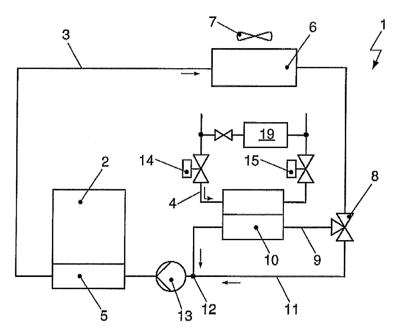
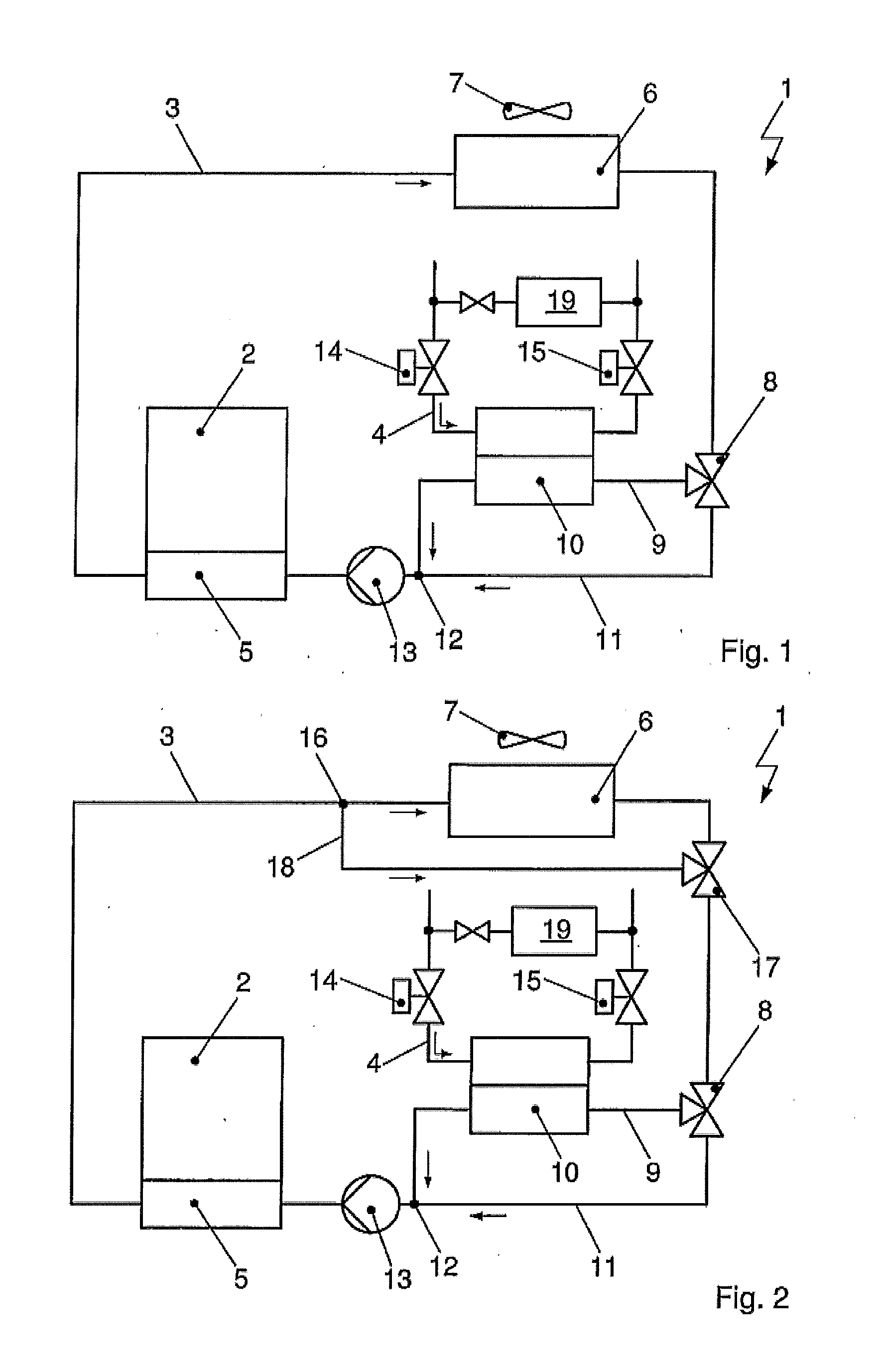
[0053]FIG. 1 shows a cooling system 1 comprising a coolant circuit 3, which is designed to cool and / or dissipate heat from a chemical energy storage device 2. In place of the energy storage device 2, which hereinafter is also referred to as a battery 2, it is also possible to thermally couple other components of the drive train of the vehicle, such as the engine of power electronics, to the cooling system 1.

[0054]The following detailed description and appended drawings describe and illustrate various embodiments of the invention. The description and drawings serve to enable one skilled in the art to make and use the invention, and are not intended to limit the scope of the invention in any manner.

[0055]The coolant circuit 3 has a pump device 13 for delivering the coolant. In the direction of flow of the coolant, a heat exchanger 5 is arranged downstream of the coolant pump, and is thermally coupled to the battery 2. Accordingly, several types of heat transfer are conceivable. The co...


PUM


Abstract

The disclosure relates to a cooling system and a method for operating the cooling system for cooling a battery of a vehicle using a coolant circuit. The cooling circuit includes a pump device, a heat exchanger for transferring heat between a coolant and the battery, a heat exchanger for transferring heat between the coolant and the surroundings, and a heat exchanger for transferring heat between the coolant and a refrigerant circulating in a refrigerant circuit. The refrigerant circuit is designed with a heat exchanger and an associated expansion element. The refrigerant circuit includes two additional expansion elements. The first expansion element is arranged upstream of the heat exchanger and the second expansion element is arranged downstream of the heat exchanger, with regard to the direction of the refrigerant flow. The heat exchangers designed as evaporators on the refrigerant side can be operated with different pressure and temperature levels.

Description

CROSS-REFERENCE TO RELATED APPLICATION[0001]This application claims the benefit of priority of German Patent Application Serial No. DE 10 2010 042 122.7-45 filed on Oct. 7, 2010, hereby incorporated herein by reference in its entirety.FIELD OF THE INVENTION[0002]The invention relates to a cooling system for cooling the battery of a vehicle, and, more particularly, to a cooling system for cooling the battery of an electric vehicle or hybrid vehicle using a coolant circuit. The invention further relates to a method for operating the cooling system.BACKGROUND OF THE INVENTION[0003]High-capacity batteries used in electric or hybrid vehicles are used to store electrical energy. The energy is supplied to the battery by connecting the battery to a power supply source. With hybrid vehicles, energy can also be recovered during the braking processes of the vehicle.[0004]During operation, both the battery cells of the battery as well as other components of the electrical drive train, such as t...

Claims


Application Information

Patent Timeline
IPC IPC(8): F01P9/00
CPCB60H1/00278B60H1/005B60H2001/00307H01M10/5095H01M10/5016H01M10/5079H01M10/5004B60L1/003B60L2240/34B60L2240/36B60L2240/545B60L58/26H01M10/613H01M10/625H01M10/6569H01M10/663Y02E60/10Y02T10/70
Inventor GRAAF, MARCWIESCHOLLEK, FLORIANREBINGER, CHRISTIANSCHROEDER, DIRK
Owner HANON SYST
Why Eureka
Try Eureka