Methods and apparatus for resistive voltage sensing in an isolated power distribution unit

a technology of resistive voltage and power distribution unit, applied in the field of voltage sensors, can solve the problems of large size, high cost, large size, etc., and achieve the effect of high accuracy, physical smallness, and low cos

Active Publication Date: 2012-04-12
RARITAN AMERICA
View PDF6 Cites 17 Cited by
  • Summary
  • Abstract
  • Description
  • Claims
  • Application Information

AI Technical Summary

Benefits of technology

[0015]Again, in one or more specific embodiments, the invention may provide a highly accurate, inexpensive, and physically small voltage sensor to provide sensed voltages across an isolation boundary in a circuit requiring isolation from primary to secondary (such as set forth in UL 60950-1). It bears repeating, however, that it is contemplated that the invention may be embodied in any number of circuits, systems, devices, etc. where UL 60950-1 compliance or other safety standards are necessary or desired.

Problems solved by technology

However, these devices do not make highly accurate sensors, and are expensive and large in size.
Disadvantages of the step down transformer (6) include its large size, high cost and significant inaccuracies.
The step down transformer (6) is large and expensive because of a number of turns of magnet wire required to handle the high voltage and low frequency of the primary AC voltage.
The step down transformer (6) is inaccurate because its magnetic inductive coupling results in output amplitude and phase shift variance between different transformers of the same make and model number.
Among the disadvantages of the optical isolator (10) is the relatively large power required to turn on its LED (10a).
Optical isolators are also inherently inaccurate, especially over temperature, and are relatively unreliable as compared with, for example, a simple resistor network.
The disadvantages of the primary powered resistive sensor measurement circuit (13) combined with the isolation circuitry (14) are, again, its cost, complexity, accuracy and / or reliability issues.
Although resistor sensors are known to exhibit inherent linearity, high accuracy, low cost and small size, such sensors have not been used to provide sensed voltages across isolation boundaries in circuits requiring isolation from primary to secondary (such as SELV circuits).
Consequently, there are no known circuits in the prior art employing resistive networks to provide sensed voltages across isolation boundaries.
Moreover, owing to the accepted wisdom in this art area, skilled artisans are not motivated to use resistive networks in such applications.
Thus, a long felt, but unsatisfied, need has developed in this area of circuit design, which has been simply accepted by those skilled in the art.

Method used


Image

  • Methods and apparatus for resistive voltage sensing in an isolated power distribution unit
  • Methods and apparatus for resistive voltage sensing in an isolated power distribution unit
  • Methods and apparatus for resistive voltage sensing in an isolated power distribution unit

Examples


Embodiment Construction

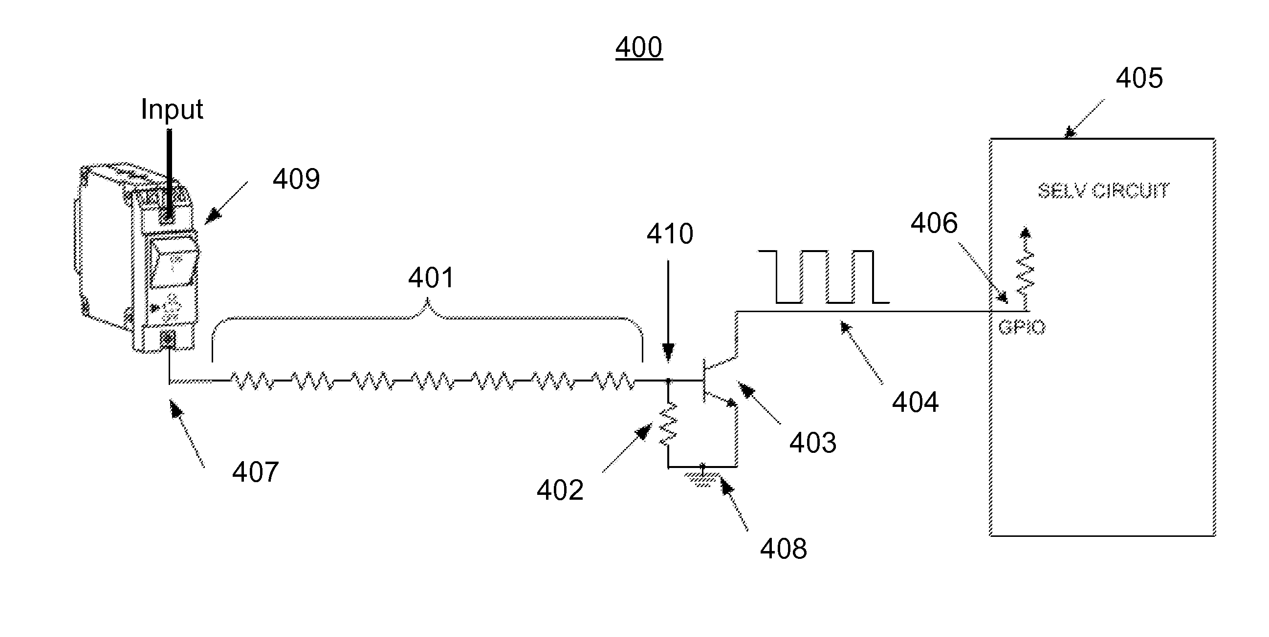
[0037]Although one or more embodiments of the invention may be designed for use in a PDU intended for IT equipment applications, and is here illustrated as used in such a PDU, this is not required. Various aspects of the invention are suitable for use in any application requiring an inexpensive, accurate, small and low power consumption voltage (or current) sensor that measures the voltage or current of a primary side source and outputs the measured value(s) across an isolation boundary to a secondary side circuit, such as a UL 60950-1 compliant SELV circuit.

[0038]FIG. 3 illustrates a preferred embodiment of the invention in a system 100, that includes a voltage sensor that performs a single ended measurement between a primary side AC main line (1) and ground (107) and outputs a scaled down AC voltage single ended SELV output (108). A single ended input, single ended output sensor is useful when measuring a primary 4-wire 3-phase AC power line (1), which includes lines (1a, 1b, 1c, ...


PUM


Abstract

Methods and apparatus provide for a primary side circuit including one or more voltage nodes; and a monitoring circuit operating to monitor one or more parameters of the primary side circuit, and including at least one sensing circuit and at least one processing circuit within a secondary side circuit, where the sensing circuit includes a resistor network having an input for receiving a first sensed voltage from a first of the voltage nodes of the primary side circuit, traversing an isolation boundary between the primary side circuit and the secondary side circuit while adhering to a safety specification, which includes a primary-secondary isolation requirement, and having an output for providing a first modified sensed voltage to the processing circuit.

Description

BACKGROUND[0001]The invention relates to voltage sensors, and more particularly relates to voltage sensors that measure AC mains voltage and output to a circuit that is safe for an operator to touch (SELV circuit). In one or more specific applications, the invention relates to highly accurate, inexpensive, and physically small voltage sensors for use in devices that are UL 60950-1 compliant, and to UL 60950-1 compliant devices that use such sensors. The following description focuses upon use of the invention in a specific context, namely a UL 60950-1 compliant power distribution unit (“PDU”) but the invention is not limited to PDU applications and can be used in other applications where UL 60950-1 compliance or other safety standards are necessary or commercially advantageous.[0002]The UL 60950-1 standard establishes requirements that reduce risks to persons who operate and service information technology equipment (“IT equipment”). Examples of IT equipment are data and text processi...

Claims


Application Information

Patent Timeline
Patent Type & Authority Applications(United States)
IPC IPC(8): G05F3/04
CPCG01R19/0084G01R15/04H02H9/06H02H9/04G01R19/16547G01R31/42H02J3/00
Inventor SUCHOFF, MICHAEL
Owner RARITAN AMERICA
Why Eureka
Try Eureka