
Imaging system for imaging a viscoelastic medium

Inactive Publication Date: 2012-04-12
KONINKLIJKE PHILIPS ELECTRONICS NV
View PDF3 Cites 2 Cited by
  • Summary
  • Abstract
  • Description
  • Claims
  • Application Information

AI Technical Summary

Benefits of technology

[0006]It would be advantageous to achieve an imaging system which is suitable for real-time monitoring of a treatment process. It would also be desirable to provide an imaging system which is capable of real-time imaging of three-dimensional properties of treated tissue during the treatment process. Furthermore, it would also be desirable to provide an imaging system which is suitable for integration with a treatment modality, such as a probe-based treatment modality. In general, the invention preferably seeks to mitigate, alleviate or eliminate one or more disadvantages of the prior art, singly or in any combination.
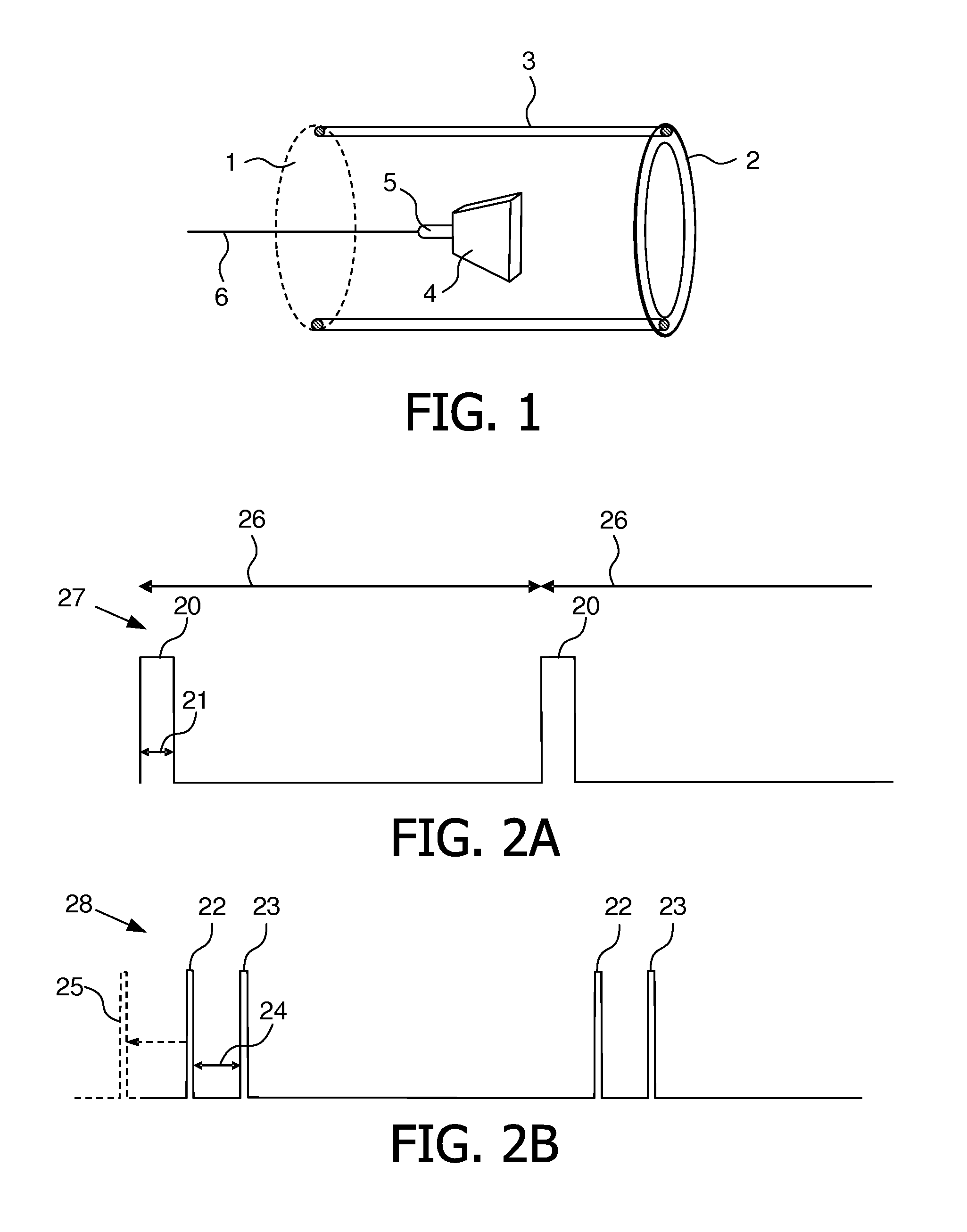
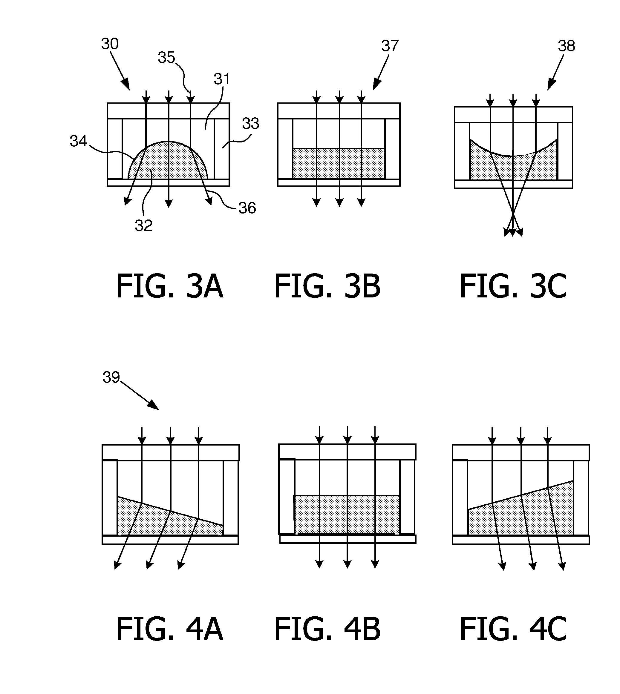
[0014]The imaging system combines acoustic radiation force imaging (ARFI) with the application of a variable refractive lens which at least supports two configurations, one configuration suitable for use in connection with displacement of the viscoelastic medium, and one configuration suitable for use in connection with imaging of the displacement of the viscoelastic medium. This combination allows building both functionalities into a single device, making it compact.
[0015]A further advantage lies therein that the image system supports integration into a conventional catheter-based probe, thereby providing a very compact imaging device suitable for minimal incision surgery.

Problems solved by technology

Catheter-based surgery, nevertheless, suffers from certain drawbacks, one example being shortcomings in real-time assessment during the surgical procedure.
For example in connection with catheter-based ablation, if the ablated tissue depth is too shallow then a relapse of the arrhythmias can take place and there may be a need for repeating the procedure, which can be very risky and costly.
On the other hand, if the ablation depth is too deep, then there is a risk of cardiac perforation which could be fatal.
Currently, however, there is no reliable way of monitoring the progression of an ablation procedure.

Method used


Image

  • Imaging system for imaging a viscoelastic medium
  • Imaging system for imaging a viscoelastic medium
  • Imaging system for imaging a viscoelastic medium

Examples


Embodiment Construction

[0029]The present invention is disclosed in connection with a radio-frequency (RF) ablation catheter comprising an imaging system in accordance with embodiments of the present invention. It is however to be understood that, while such a configuration is advantageous, the invention is not limited to this. In fact, the imaging system may be applied in connection with any modality which alters the elastic properties of the viscoelastic medium under treatment. In particular, the imaging system may be used in connection with a catheter-based probe, such as a catheter-based ablation probe, e.g. RF ablation, high intensity focused ultrasound (HIFU) or cryo-ablations.

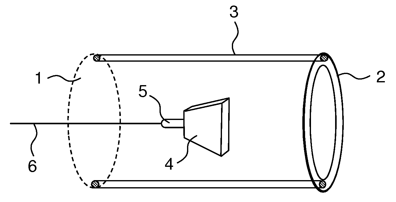
[0030]FIG. 1 schematically illustrates the distal end of an RF ablation catheter-based probe, hereafter simply referred to as a catheter. The Figure illustrates the catheter housing 1, the ablation ring 2 with feed wires 3, a variable refractive lens 4 in the form of a fluid focus lens assembly and an acoustic transducer 5 and ...


PUM


Abstract

An imaging system for imaging a viscoelastic medium is disclosed. The imaging system comprises a variable refractive lens (4) and a transducer system (5) for generating acoustic radiation. The imaging system is operated to alternate between first and second operating modes. While the variable refractive lens is operated to alternate between a first configuration and a second configuration, the transducer is operated to alternate between generating acoustic radiation for displacing the viscoelastic medium and acoustic radiation for imaging the displacement of the viscoelastic medium. In embodiments the variable refractive lens is a fluid focus lens. Moreover, in embodiments, the imaging system is integrated with a catheter-based interaction modality, such as a tissue ablation modality.

Description

FIELD OF THE INVENTION[0001]The present invention relates to an imaging system for imaging a viscoelastic medium based on application of acoustic radiation.BACKGROUND OF THE INVENTION[0002]Catheter-based surgery is advantageously used in various connections to treat body organs with minimal incision size and clearance of the organs. As an example, cardiac arrhythmias may be treated by various catheter-based ablation techniques to remove part of the cardiac tissue. Specifically, radio-frequency (RF) ablation, high intensity focused ultrasound (HIFU) or cryo-ablations of the tissue are commonly used.[0003]Catheter-based surgery, nevertheless, suffers from certain drawbacks, one example being shortcomings in real-time assessment during the surgical procedure. For example in connection with catheter-based ablation, if the ablated tissue depth is too shallow then a relapse of the arrhythmias can take place and there may be a need for repeating the procedure, which can be very risky and c...

Claims


Application Information

Patent Timeline
IPC IPC(8): H04N7/18
CPCA61B2019/5276G01S15/8911G10K11/30A61B8/445A61B8/12A61B8/4281A61B18/1492A61B5/0048A61B5/0053A61B2090/378
Inventor SHAHZAD, KHALIDANAND, AJAYPETRUZZELLO, JOHNZHOU, SHIWEISUIJVER, JAN FREDERIK
Owner KONINKLIJKE PHILIPS ELECTRONICS NV
Learn More