
Constant Volume Combustion Chamber

a combustion chamber and constant volume technology, applied in the field of constant volume combustion chambers and combustors, can solve the problems of pulse detonation combustors, constant pressure combustors may experience reduced efficiency, and the effect of reducing pressure, avoiding excessive pressure, and reducing the size of the combustion chamber

Inactive Publication Date: 2012-12-20
STREAMLINE AUTOMATION LLC
View PDF13 Cites 17 Cited by
  • Summary
  • Abstract
  • Description
  • Claims
  • Application Information

AI Technical Summary

Benefits of technology

[0013]Embodiments of the present invention preferably seek to mitigate, alleviate or eliminate one or more disadvantages or issues in the art such as the above-identified, singly or in any combination, by providing a combustor, system, a method, and a computer-readable medium that provide for improved operational performance relative to existing constant volume combustion chambers, including higher combustion chamber and pulse pressures, higher cycling rates, and greater reliability, according to the appended patent claims.
[0017]Advantages of the constant volume combustion cycle relative to pulse detonation combustors include simpler ignition systems and absence of extremely high pressures resulting from detonation. Advantages of the constant volume combustion cycle over conventional liquid bipropellant constant-pressure combustion cycles include lower pressure in the chamber during injection and improved Isp for a given system supply pressure.

Problems solved by technology

Fuel and oxidizer are injected into the combustion chamber in pulses, resulting in sequential detonations that create pressure pulses of exhaust from a nozzle.
Constant pressure combustors may experience reduced efficiency as ambient pressure changes, for example with altitude.
In these cases, the pintle or plug must never seal the combustion chamber because the fuel and oxidizer enter the combustion chamber at a near steady rate and blocking the exhaust during normal operation would result in an explosion.
Pulse detonation combustors suffer from drawbacks associated with structural requirements to prevent failure and the complexity of fuel delivery and ignition systems required to obtain properly timed detonations.
The improvement mitigates some of the drawbacks associated with detonation-type combustion and resulting shock waves, but the ignition system of such a combustor remains relatively complex in order to obtain complete combustion during each pulse before combustion products escape the open end of the combustion chamber.
A simple pintle without a canted coil is disclosed in the '487 patent in an example as being “non-optimal” because of expected wear that would prevent adequate sealing of the chamber.
The combustor of the constant volume rocket motor disclosed in the '487 patent is limited with respect to the need for a canted coil pintle to prevent wear on surfaces used to seal the combustion chamber and effectively sealing the combustion chamber during combustion at very high pressures, such as pressures above 700 PSI.

Method used


Image

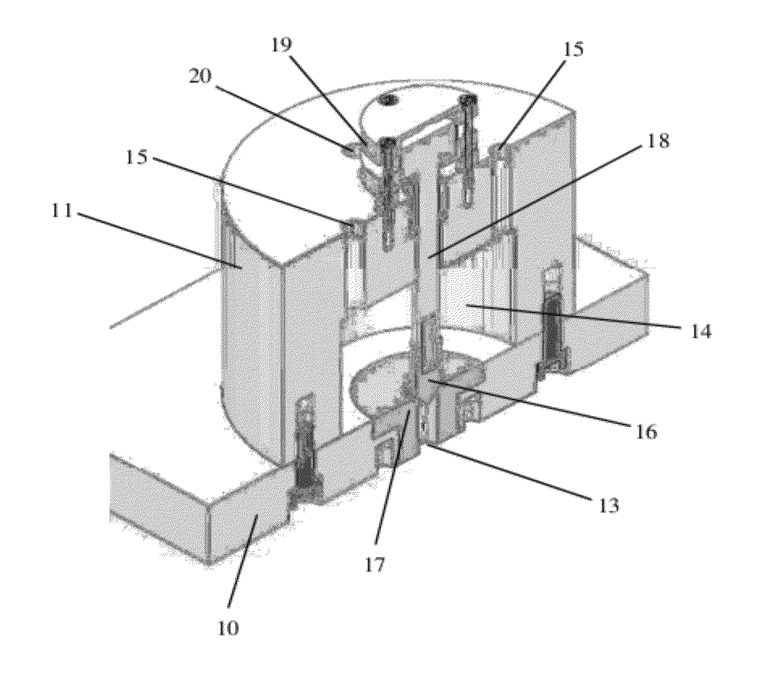
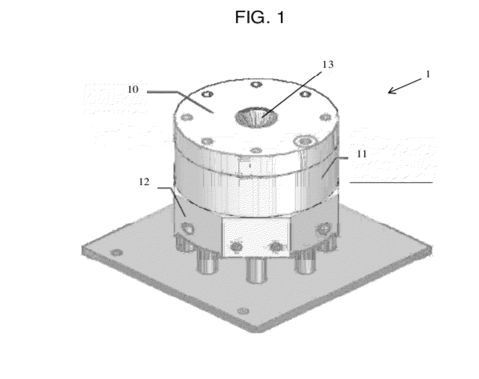
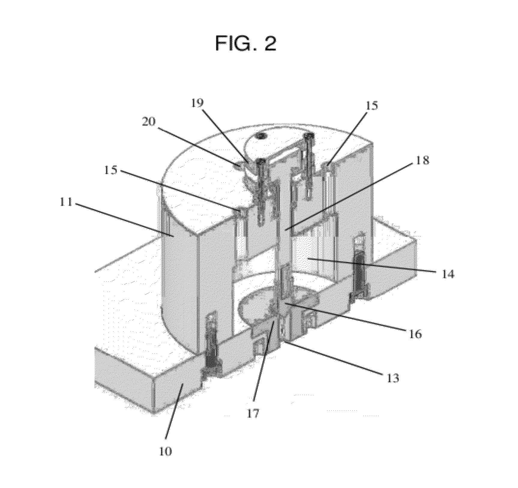
  • Constant Volume Combustion Chamber
  • Constant Volume Combustion Chamber
  • Constant Volume Combustion Chamber

Examples


example

[0038]A combustor according to the embodiment shown in FIG. 3 was tested using propane and nitrous oxide as fuel and oxidizer propellants. Two tanks, one for each propellant, were connected to four paired oxidizer and fuel injectors through oxidizer and fuel manifolds and fuel and oxidizer valves. The pintle head and nozzle throat were constructed with a taper angle of 15 degrees and a roughness of 32 microinches. The travel distance of the pintle head was set to 0.25 inches. The computer readable controller code in this example was located in a separate computer control unit and controlled fuel supply, oxidizer supply, ignitor firing, and exhaust release and monitored cycle count and cycle completion, and temperature and pressure in the combustion chamber measured by temperature and pressure sensors. The combustor was manually set to produce sequential impulse bits using a variety of pressures, delays, and durations for propellant injection and exhaust release and cycle numbers and...


PUM


Abstract

A constant volume combustion chamber, combustor, and method for constant volume combustion involve combusting a fuel in a chamber sealed by a pintle having a conical portion fitted into a conical nozzle throat and pulling the pintle away from the nozzle throat to allow combustion products to exhaust through a nozzle outlet. The shapes and surfaces of the pintle and nozzle throat provide for sealing the chamber at high pressures while resisting surface wear. Operational parameters for the combustor may be computer controlled in response to measured pressures and temperatures in the combustor.

Description

RELATED APPLICATIONS[0001]This application is a non-provisional of and claims priority to U.S. application Ser. No. 61 / 498,742, filed Jun. 20, 2011, which is incorporated by reference in its entirety.FEDERALLY SPONSORED RESEARCH OR DEVELOPMENT[0002]The U.S. Government has certain rights to this invention pursuant to Contract Number NNX10CE13P awarded by the National Aeronautics and Space Administration.BACKGROUND OF THE INVENTION[0003]1. Field of the Invention[0004]The present invention relates to constant volume (CV) combustion chambers and combustors and methods for their operation.[0005]2. Description of Related Art[0006]Constant volume combustion is fundamentally different and operates on a different principle from constant pressure combustion. A constant pressure combustor uses an open combustion chamber and high pressure is maintained in the combustion chamber during combustion by supplying high-pressure fuel and oxidizer to the combustion chamber.[0007]A pulse detonation comb...

Claims


Application Information

Patent Timeline
IPC IPC(8): F02K1/08F02K9/52F16K1/00F02K1/15
CPCF02K9/52F02K9/58F02K9/62F23C2900/03005F23R7/00F23C99/00F16K1/385F23C3/00
Inventor DI SALVO, ROBERTODOHERTY, STEPHENREICH, ALTON J.
Owner STREAMLINE AUTOMATION LLC
Learn More