Flame linkage system of fuel gas radiation pipes

A radiant tube and combined flame technology, applied in the field of gas regenerative combustion equipment, can solve the problems of cumbersome manual operation, high cost and huge system, and achieve the effects of simple control system, convenient operation and simplified ignition system

Pending Publication Date: 2017-05-24
SHENWU TECH GRP CO LTD
View PDF0 Cites 0 Cited by
  • Summary
  • Abstract
  • Description
  • Claims
  • Application Information

AI Technical Summary

Problems solved by technology

[0004] Aiming at the deficiencies of the prior art, the present invention designs and develops a gas radiant tube combustion system with a cross-flame device, which solves the problem that the current gas radiant tube needs to be equipped with a large number of ignition burners and corresponding ignition control systems. The system is very large and requires manual operation. Technical issues such as cumbersome and high cost

Method used


Image

  • Flame linkage system of fuel gas radiation pipes
  • Flame linkage system of fuel gas radiation pipes

Examples


Embodiment Construction

[0022] In order to enable those skilled in the art to better understand the technical solutions of the present invention, the present invention will be further described in detail below in conjunction with specific examples. The embodiments described below are exemplary only for explaining the present invention and should not be construed as limiting the present invention. If no specific technique or condition is indicated in the examples, it shall be carried out according to the technique or condition described in the literature in this field or according to the product specification.

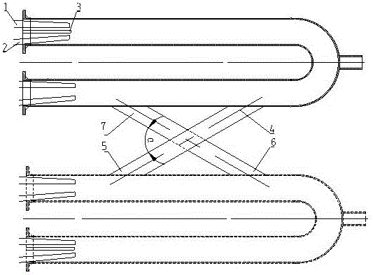
[0023] According to one aspect of the present invention, the present invention provides a cross-fire system for gas radiant tubes, figure 1 It is the overall structure diagram of the co-fired system of the gas radiant tube, such as figure 1 As shown, the system includes: multiple radiant tubes and multiple cross-fire devices, at least one cross-fire device is arranged between two adjacent rad...


PUM


Abstract

The invention provides a flame linkage system of fuel gas radiation pipes. The flame linkage system comprises the multiple radiation pipes and a plurality of flame linkage devices. At least one flame linkage device is arranged between every two adjacent radiation pipes. Each flame linkage device comprises two channels arranged in a crossed manner, wherein the first channel is provided with a first high-temperature smoke inlet and a first high-temperature smoke outlet, the first high-temperature smoke inlet is connected with the corresponding ignited radiation pipe, the first high-temperature smoke outlet is connected with the corresponding adjacent radiation pipe, and the included angle is formed between the first channel and the second channel. The flame linkage system is simple in structure and convenient to operate, the control system cost and work intensity are reduced, a radiation pipe combustor ignition system is simplified, and burner producing and running cost is reduced to the great degree. Meanwhile, the combustion system is stable, and the phenomenon that due to instable ignition burner flame monitoring signals at present, a fuel gas valve is frequently cut off cannot occur.

Description

technical field [0001] The invention belongs to the field of gas heat storage combustion equipment, and in particular relates to a gas radiant tube combustion system with a co-flame device. Background technique [0002] The gas radiant tube mainly uses coal gas as fuel, burns in a special sealed casing, and transfers heat to the heated object in the form of heat radiation through the heated casing surface, and the combustion product does not contact the heated object; regenerative gas The radiant tube uses the sensible heat of the flue gas after combustion in the casing to preheat the combustion air or gas through the arrangement of the regenerator. It has the characteristics of high combustion thermal efficiency, stable operation, and high equipment reliability. It is widely used in various heat treatment furnaces and continuous annealing furnaces. stove etc. [0003] Due to the normal working process of the gas radiant tube, it is necessary to configure the corresponding ...

Claims


Application Information

Patent Timeline
Patent Type & Authority Applications(China)
IPC IPC(8): F23D14/12F23D14/72
CPCF23D14/12F23D14/72
Inventor 钟贵全陈珊宋敏洁王东方郭科宏吴道洪
Owner SHENWU TECH GRP CO LTD
Why Eureka
Try Eureka