Cutting Insert and Indexable Face Mill

Active Publication Date: 2012-04-12
TUNGALOY CORP
View PDF5 Cites 12 Cited by
  • Summary
  • Abstract
  • Description
  • Claims
  • Application Information

AI Technical Summary

Benefits of technology

[0009]To resolve this problem, one objective of the present invention is to provide a cutting insert that can be employed both for a left hand cut and a right hand cut, and for which the chipping resistances of minor cutting edges and adjacent portions are improved, in order to obtain a better surface roughness for a work surface, and an indexable face mill.

Problems solved by technology

Since as described above the strength of the adjacent portions is lowered, the load due to micro-cutting is easily imposed on these portions, and chipping tends to occur.
Therefore, there is a probability that the chipped minor cutting edges and the clearance parts will contact the work surface and degrade the surface roughness of the work surface.

Method used


Image

  • Cutting Insert and Indexable Face Mill
  • Cutting Insert and Indexable Face Mill
  • Cutting Insert and Indexable Face Mill

Examples


Embodiment Construction

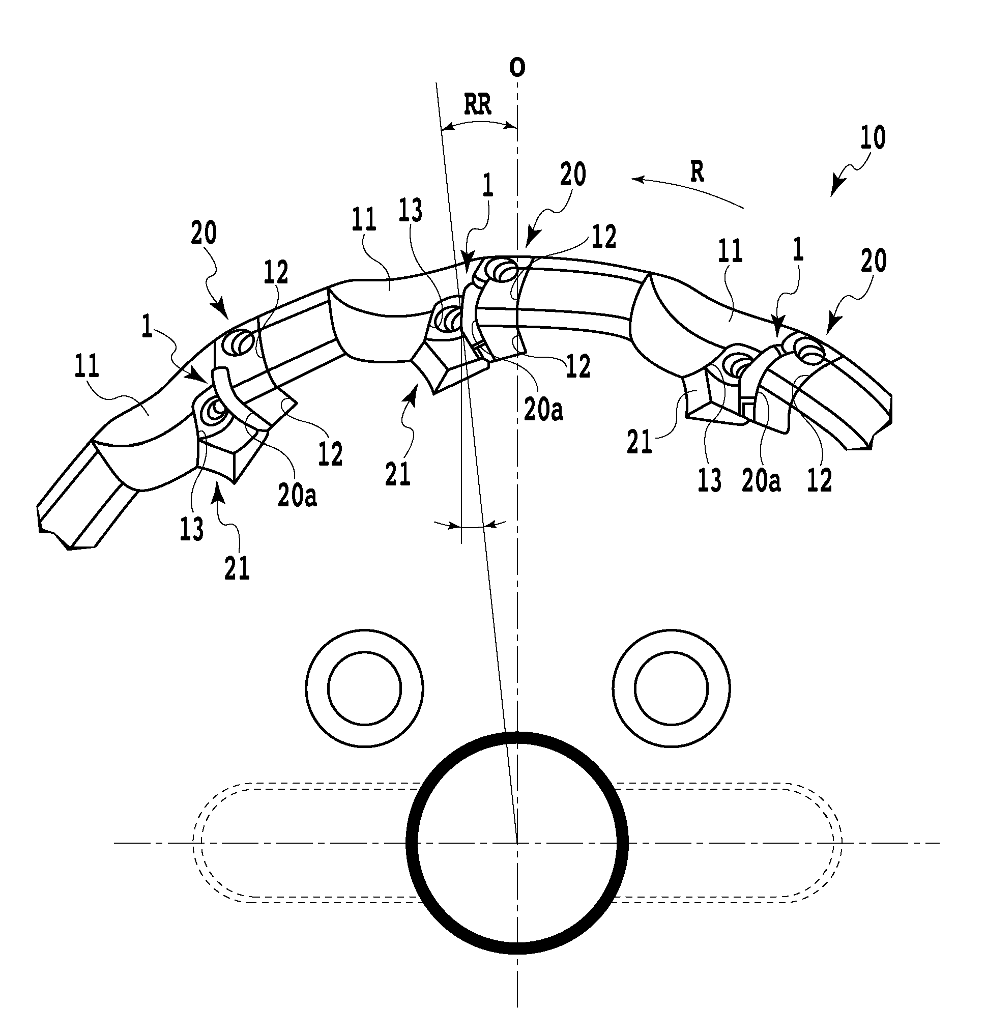
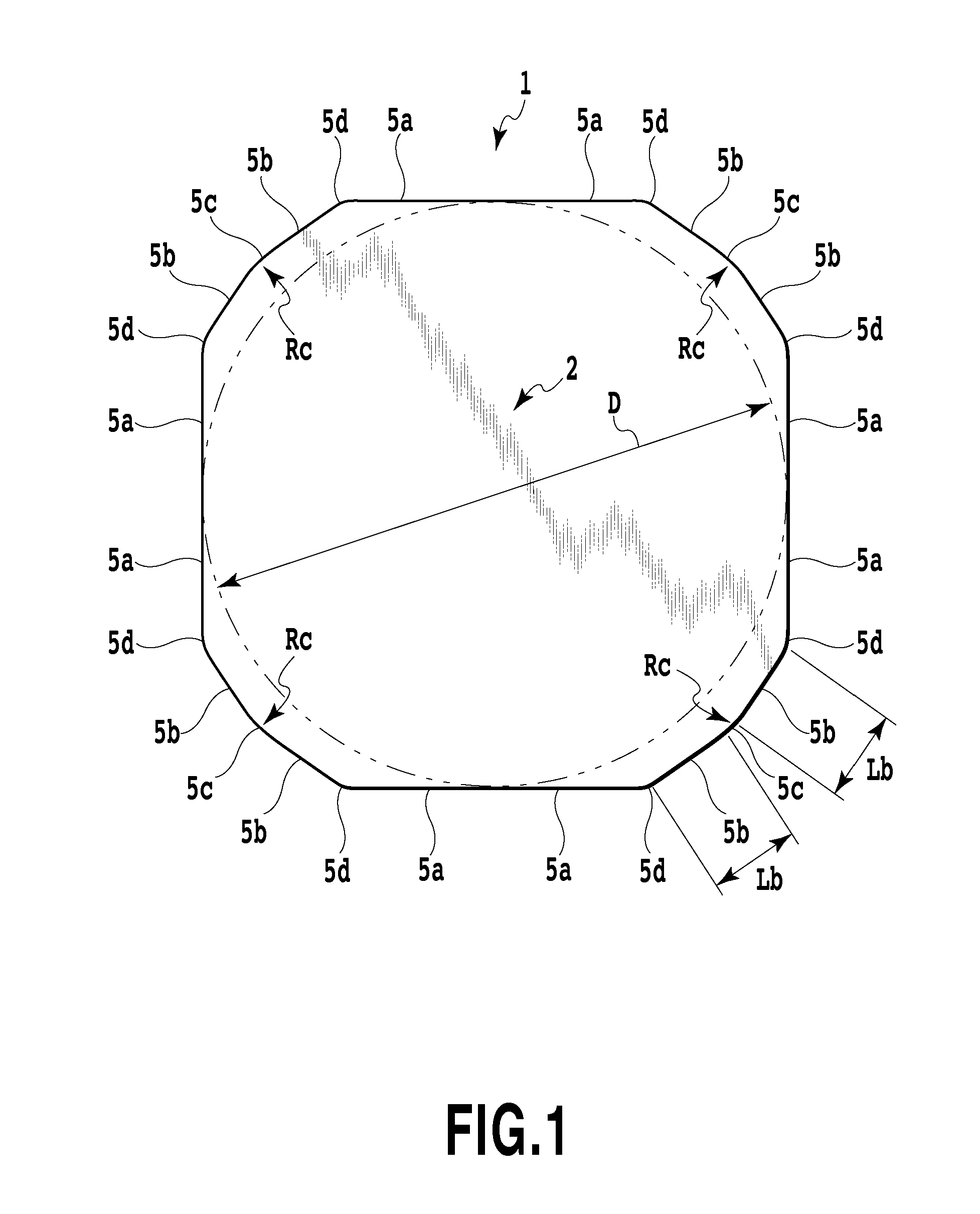
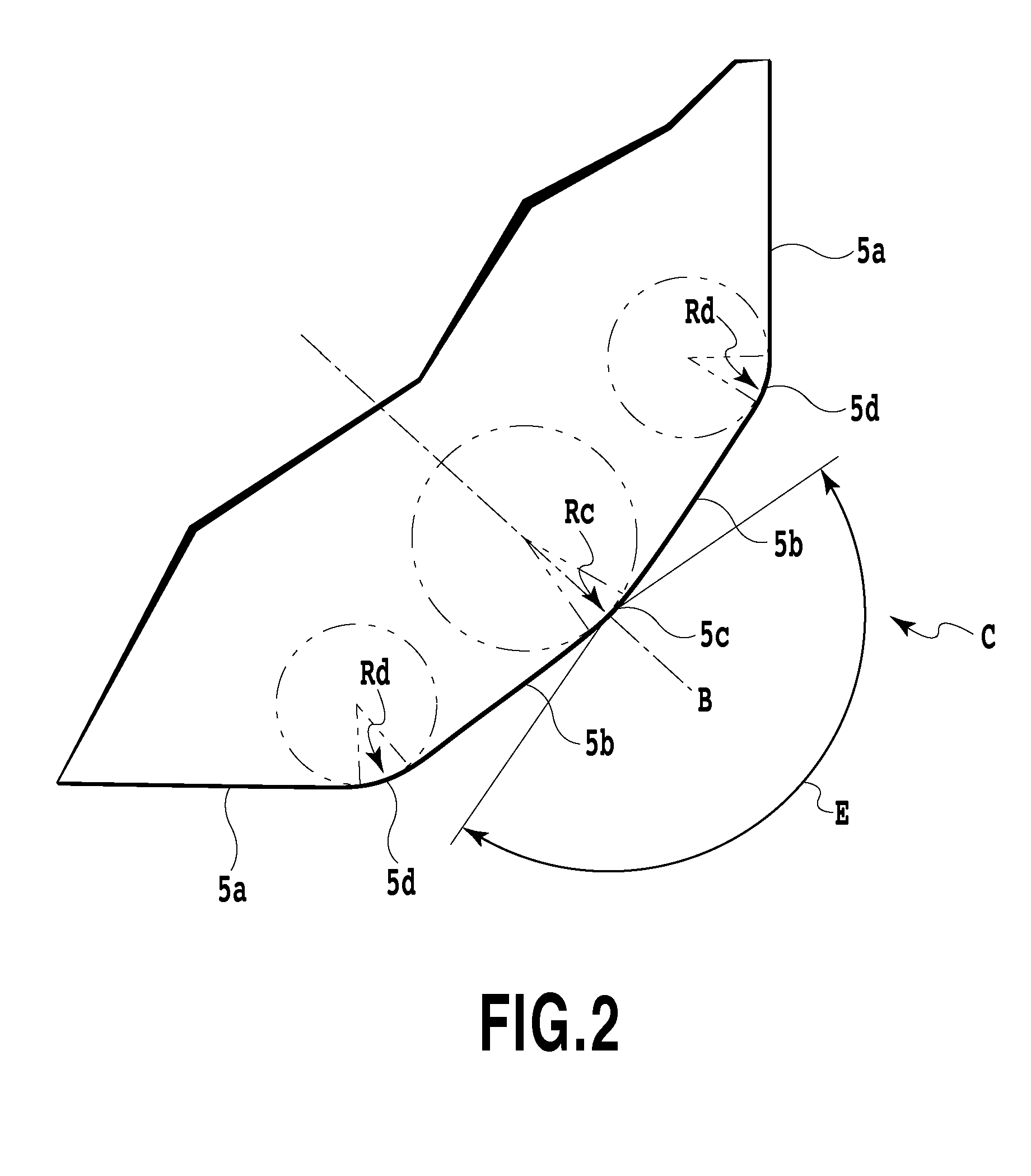
[0041]A cutting insert according to one embodiment of the present invention is an exemplary cutting insert to be mounted on a face mill having an approach angle of 48°. As shown in FIGS. 1 to 3, an insert body 1 is a plate having an almost square shape. The almost square upper face of the insert body 1 serves as a rake surface 2, the lower face opposite the upper face serves as a substantially flat seat surface 3, and the side faces extended between the upper and lower faces serve as flank surfaces. The inscribed circle diameter D of the almost square upper face is 12.7 mm. The intersecting ridge portions of the rake surface 2 and the flank surfaces serve as cutting edges. The side surfaces employed as the flank surfaces are gradually inclined to the interior of the insert body 1 in a direction from the intersecting portion of the upper face to the intersecting portion of the lower face, and a positive flank angle is formed. The rake surface 2 of the insert body 1 is provided as a f...


PUM

PropertyMeasurementUnit
Lengthaaaaaaaaaa
Lengthaaaaaaaaaa
Angleaaaaaaaaaa

Abstract

A pair of sub-flank surfaces is formed at a vertex angle portion of an insert body having a substantially polygonal, plate-like shape, and between the sub flank surfaces, a vertex flank surface at a vertical angle portion is formed substantially in a protrusive, curved shape, and is smoothly connected to the sub-flank surfaces in a tangential direction. The vertex flank surface at the vertex angle portion is extended across the entire thickness of the insert body, and boundary lines, between the vertex flank surface at the vertex angle portion and a pair of minor cutting edges, are parallel to each other. A second curved ridge line, which is formed between (i) the flank surface and (ii) the rake surface, and a first curved ridge line, which is formed between (i) the flank surface and (ii) the seat surface, have approximately same shape.

Description

CROSS-REFERENCE TO RELATED APPLICATIONS[0001]This application is a Continuation of PCT application No. PCT / JP2010 / 059971 filed Jun. 11, 2010 and published as WO 2010 / 147065 on Dec. 23, 2010, which claims the benefit of Japanese Patent Application No. 2009-142826, filed Jun. 16, 2009. The aforementioned patent applications are incorporated by reference herein in their entirety.BACKGROUND OF THE INVENTION[0002]1. Field of the Invention[0003]The present invention relates to a cutting insert and an indexable face mill on which such cutting inserts are mounted.[0004]2. Description of the Related Art[0005]Cutting inserts have been proposed that are available both for a case wherein, when the cutting inserts are mounted on a face mill, they are to be fed to the right of the inserts, as viewed from the front in the rotational direction of the tool (hereinafter, this is referred to as a right hand cut), and for a case wherein they are to be fed to the left of the inserts, as viewed from the ...

Claims


Application Information

Patent Timeline
IPC IPC(8): B23C5/20B23B27/16
CPCB23C5/06B23C5/207B23C2210/0435B23C2210/045Y10T407/23Y10T407/1924Y10T407/1962Y10T407/235B23C5/20B23C5/202B23B27/14
Inventor UNO, KAZUYUKINISHIYA, NAOTO
Owner TUNGALOY CORP
Why Eureka
Try Eureka