Method for Defining a Dental Framework Design Volume
a design volume and dental framework technology, applied in the field of dental frameworks, can solve the problems of inability to properly visualize the spatial volume, time-consuming additional modifications, and often required additional modifications, and achieve the effect of avoiding further processing of the framework or denture teeth
- Summary
- Abstract
- Description
- Claims
- Application Information
AI Technical Summary
Benefits of technology
Problems solved by technology
Method used
Image
Examples
first embodiment
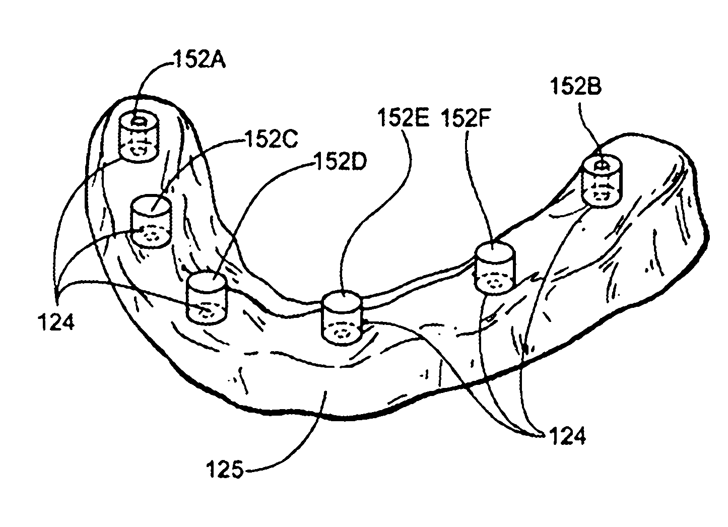
[0214]In first embodiment of the improved method, the diagnostic wax up is created, then modified and used to determine the ideal volume for the placement of a framework. In the first embodiment, after the diagnostic wax up 130 is created, the denture teeth 132 are removed, as shown in FIG. 37, from the diagnostic wax up 130 leaving a body representing the maximum available design body 334 as shown without the stone cast 125 in FIG. 38. The maximum available design body 334, if used without further modification, may represent the dental framework design volume which in turn is defined by a lower limit surface 336, here representing the soft tissue contours captured by the stone cast125, an upper limit surface 337, here representing the lower surface of the denture teeth 132, a facial limit surface 338, here representing the facial surface boundary defined by the diagnostic wax up 130 or facial index 142, and a lingual limit surface boundary 339 representing the lingual boundary of t...
third embodiment
[0220]FIG. 44 is a flowchart of the invention showing a method where the denture teeth 132 digital models are aligned to an opposing stone cast digital model. This process is similar to the above mentioned methods to create a dental framework design volume, but differs in the fact that no diagnostic wax up 130 need be provided by the technician or dentist. Instead, step 380 begins with the customer taking impressions and recording the vertical and centric measurements for articulator set up. Next, in step 382, the stone cast 125 with analogs and a second stone cast of the opposing arch are generated for use within the articulator with the vertical and centric measurements defined by the customer. In step 384, the stone cast of the arch which the framework is intended to be designed for is scanned separately such as in the methods disclosed above. Also in step 384 a high resolution scan of the second stone cast of the opposing arch is generated. Finally in step 386 a third scan is ta...
second embodiment
[0222]In a second embodiment utilizing CT technology, the dentist or technician can utilize anatomical structures and landmarks including the patient's jaw and skull to orient the denture tooth models in their appropriate position. In this methodology, one can forego the creation of a radiographic stent during the scanning process or utilize one to better determine the soft tissue boundaries of the patient. Once the denture teeth models are aligned in their proper position, a dental framework design volume can be defined between the underside of the denture teeth models and the surface contours of the arch for which the dental framework is to be designed for as done above. The dental framework may then be designed within the dental framework design volume as explained above.
[0223]In a third embodiment utilizing CT technology the design volume is obtained a series of CT scans. In this final embodiment in utilizing CT data, the dentist or technician can utilize a previous first CT sca...
PUM
 Abstract
Description
Claims
Application Information
 - R&D
- Intellectual Property
- Life Sciences
- Materials
- Tech Scout
- Unparalleled Data Quality
- Higher Quality Content
- 60% Fewer Hallucinations
Browse by: Latest US Patents, China's latest patents, Technical Efficacy Thesaurus, Application Domain, Technology Topic, Popular Technical Reports.
© 2025 PatSnap. All rights reserved.Legal|Privacy policy|Modern Slavery Act Transparency Statement|Sitemap|About US| Contact US: help@patsnap.com


