
Systems and methods for supplying fuel to a gas turbine

Active Publication Date: 2012-04-19
GENERAL ELECTRIC CO
View PDF20 Cites 15 Cited by
  • Summary
  • Abstract
  • Description
  • Claims
  • Application Information

AI Technical Summary

Benefits of technology

[0011]Additional systems, methods, apparatus, features, and aspects are realized through the techniques of various embodiments of the invention. Other embodiments and aspects of the invention are described in detail herein and are considered a part of the claimed invention. Other embodiments and aspects can be understood with reference to the description and the drawings.

Problems solved by technology

Liquids forming within the condensed fuel gases may produce serious detrimental effects in the combustors, thereby resulting in hardware damage.
However, during startup operations, heat is not readily available from the gas turbine 12, thus requiring a second heat exchanger 20 with an independent heat source 24.
The need for a second heat exchanger with an independent heat source to supply heat during start up operations requires additional capital costs in the construction of the gas turbine system.
Moreover, the power consumed by the second heat exchanger to superheat the fuel decreases the overall efficiency of the gas turbine plant.

Method used


Image

  • Systems and methods for supplying fuel to a gas turbine
  • Systems and methods for supplying fuel to a gas turbine
  • Systems and methods for supplying fuel to a gas turbine

Examples


Embodiment Construction

[0019]Illustrative embodiments of the invention now will be described more fully hereinafter with reference to the accompanying drawings, in which some, but not all embodiments of the invention are shown. Indeed, the invention may be embodied in many different forms and should not be construed as limited to the embodiments set forth herein; rather, these embodiments are provided so that this disclosure will satisfy applicable legal requirements. Like numbers refer to like elements throughout.

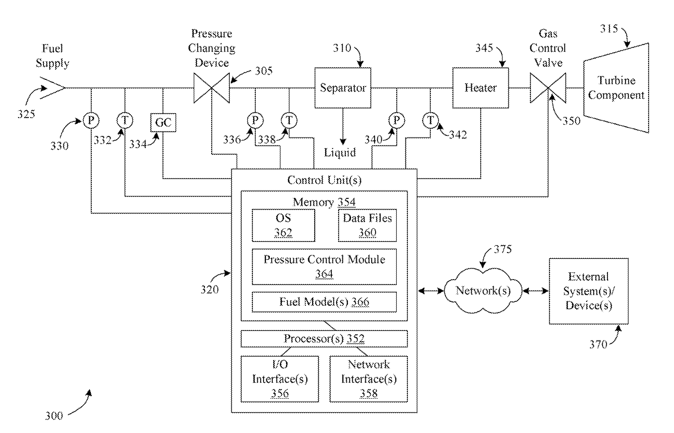
[0020]Disclosed are systems and methods for supplying fuel to a gas turbine. According to an example embodiment of the invention, a supply of fuel may be received, and characteristics and / or parameters associated with the fuel may be determined. For example, a composition of the fuel may be determined utilizing a gas chromatograph or other suitable device. As another example, a pressure and / or temperature of the fuel may be measured. Based upon the characteristics and / or parameters of the fuel, ...


PUM


Abstract

Systems and methods for supplying fuel to a gas turbine are described. A fuel may be received, and one or more parameters associated with the received fuel may be determined. Based at least in part upon the determined one or more parameters, a desired pressure for removing one or more liquids from the fuel utilizing a separator may be calculated. The operation of a pressure changing device may then be controlled in order to achieve the desired pressure. In certain embodiments, the operations of the method may be performed by a controller that includes one or more computers.

Description

FIELD OF THE INVENTION[0001]Embodiments of the invention relate generally to gas turbines and more specifically to gas turbine fuel systems.BACKGROUND OF THE INVENTION[0002]Gas turbines are widely used in a variety of commercial operations, such as power generation operations. Gas turbines generally include a compressor, one or more combustors, and a turbine component. Typically, the compressor progressively compresses a working fluid and discharges the compressed working fluid to the combustors. The combustors inject fuel into the flow of compressed working fluid and ignite the mixture to produce combustion gases having a relatively high temperature, pressure, and velocity. The combustion gases exit the combustors and flow to the turbine component where they expand to produce work which may be converted into electrical power.[0003]Liquids forming within the condensed fuel gases may produce serious detrimental effects in the combustors, thereby resulting in hardware damage. Accordin...

Claims


Application Information

Patent Timeline
IPC IPC(8): F02C7/22
CPCF02C3/22F02C7/22F02C9/40F05D2270/301F23N2021/10F23K5/00F23N1/002F23K2401/201F05D2270/303F23N2221/10F23K2400/201
Inventor BILTON, TIMOTHY RUSSELLMOSS, DANIEL MARTINRENDO, KOREY FREDERICWILKES, COLIN
Owner GENERAL ELECTRIC CO
Features
  • Generate Ideas
  • Intellectual Property
  • Life Sciences
  • Materials
  • Tech Scout
  • Unparalleled Data Quality
  • Higher Quality Content
  • 60% Fewer Hallucinations
Learn More