

Heat recovery system
a heat recovery and cooling system technology, applied in the direction of positive displacement liquid engines, heating types, lighting and heating apparatuses, etc., can solve the problems of not being able to adjust the feedwater or its amount according to a use load, not being able to cool compressed air and lubricant, and not having the existing cooling system originally provided for the compressor
- Summary
- Abstract
- Description
- Claims
- Application Information
AI Technical Summary
Benefits of technology
Problems solved by technology
Method used
Image

Examples
first preferred embodiment
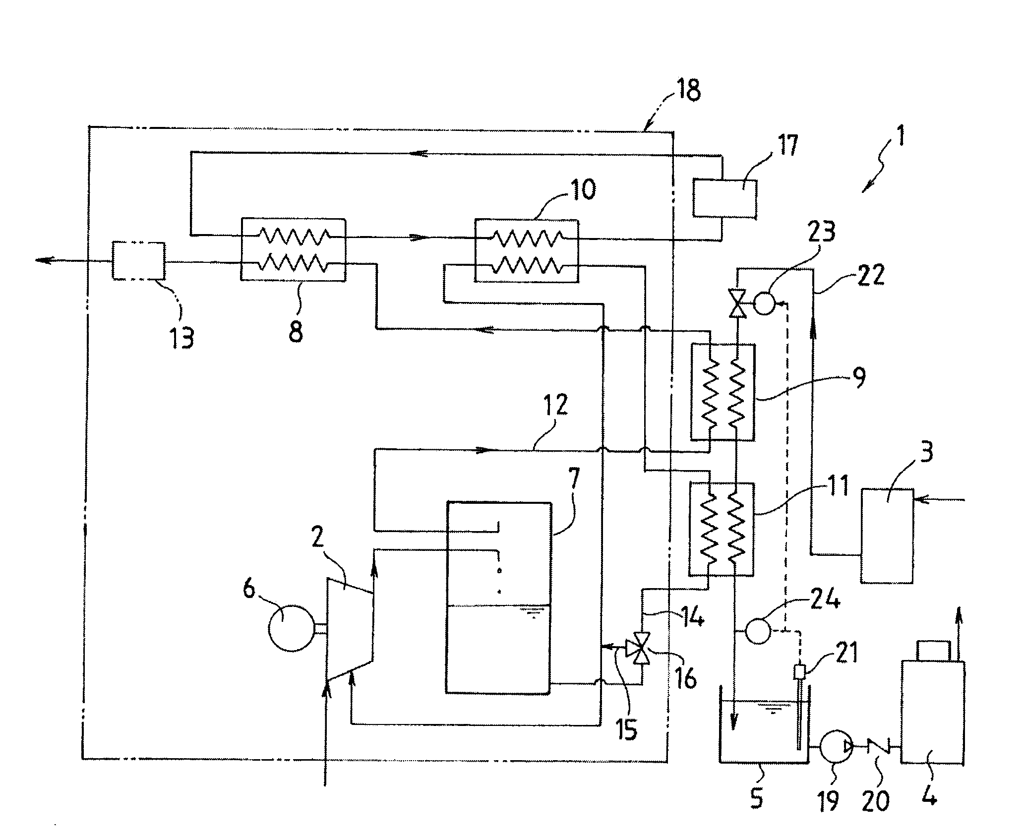
[0036]FIG. 1 is a view schematically showing a heat recovery system in a first preferred embodiment according to the present invention.
[0037]A heat recovery system 1 in the present preferred embodiment is a system for recovering the heat of compression in an oil lubrication type (oil supply type) and water cooling type motor air compressor. Specifically, the heat recovery system 1 is adapted to cool compressed air or a lubricant and heat feedwater to a feedwater tank 5 by indirectly exchanging heat between the compressed air or the lubricant from a compressor 2 and feedwater from a water softener 3 to the feedwater tank 5 in a boiler 4.
[0038]The heat recovery system 1 in the present preferred embodiment includes, as essential components; the compressor 2 for taking in, compressing, and discharging outside air; a motor 6 for driving the compressor 2; an oil separator 7 for separating the lubricant from the compressed air; a first air cooler 8 and a second air cooler 9 for cooling the...
second preferred embodiment
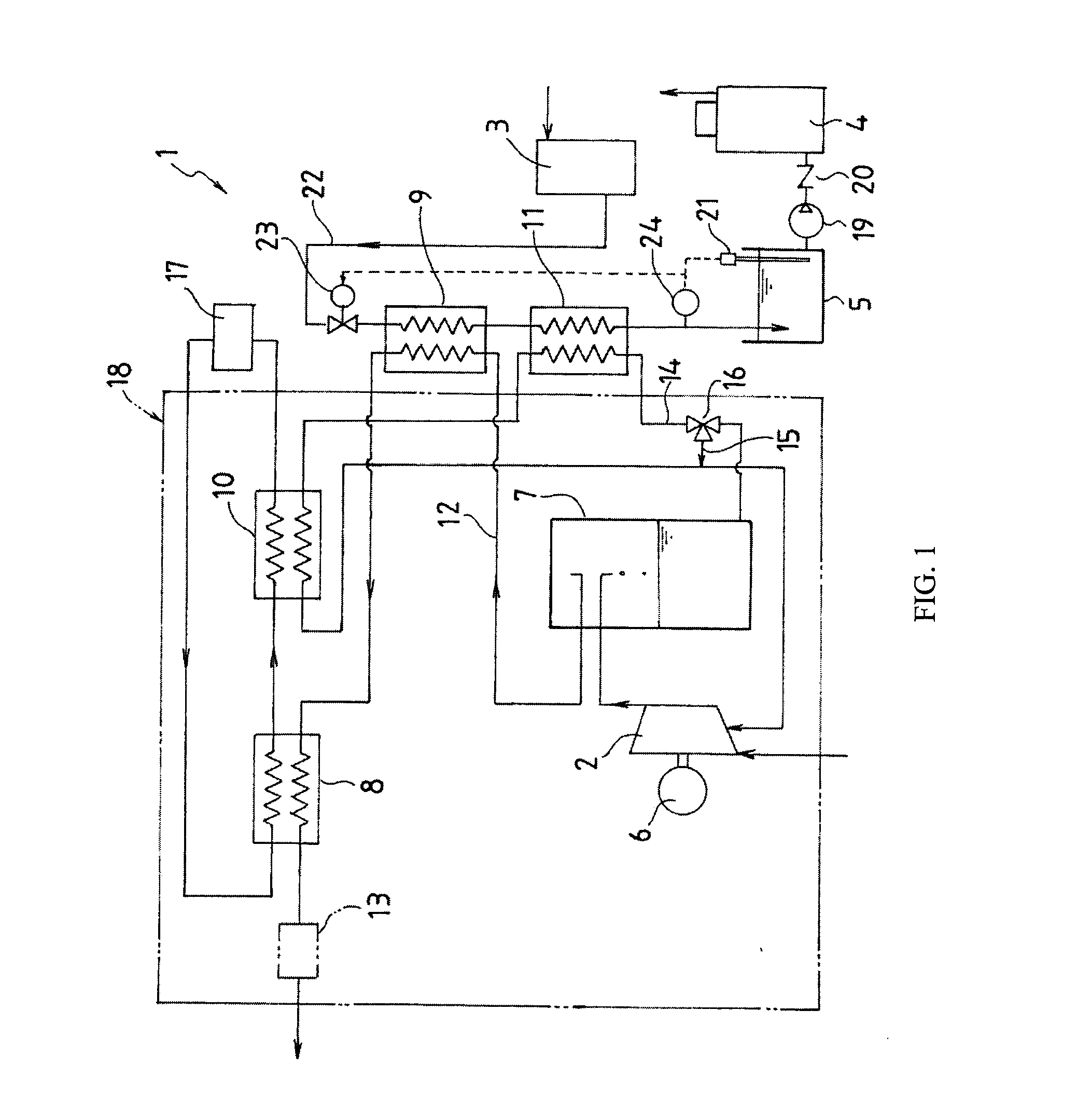
[0055]FIG. 2 is a view schematically showing a heat recovery system 1 in a second preferred embodiment according to the present invention.
[0056]The heat recovery system 1 in the second preferred embodiment also is basically similar to the heat recovery system 1 in the first preferred embodiment. Hence, a description will be mainly given of differences between the first and second preferred embodiments. The same component parts are designated by the same reference numerals.
[0057]In the first preferred embodiment, all of the compressed air from the compressor 2 is fed to the first air cooler 8 via the second air cooler 9. In contrast, in the second preferred embodiment, the second air cooler 9 can be switched or the distribution rate can be changed by switching the second air cooler 9. For the purpose of this, a bypass air feed path 25 connects the inlet and outlet of the second air cooler 9 to each other, and further, a three-way valve 26 is disposed at a branch portion between the a...
third preferred embodiment
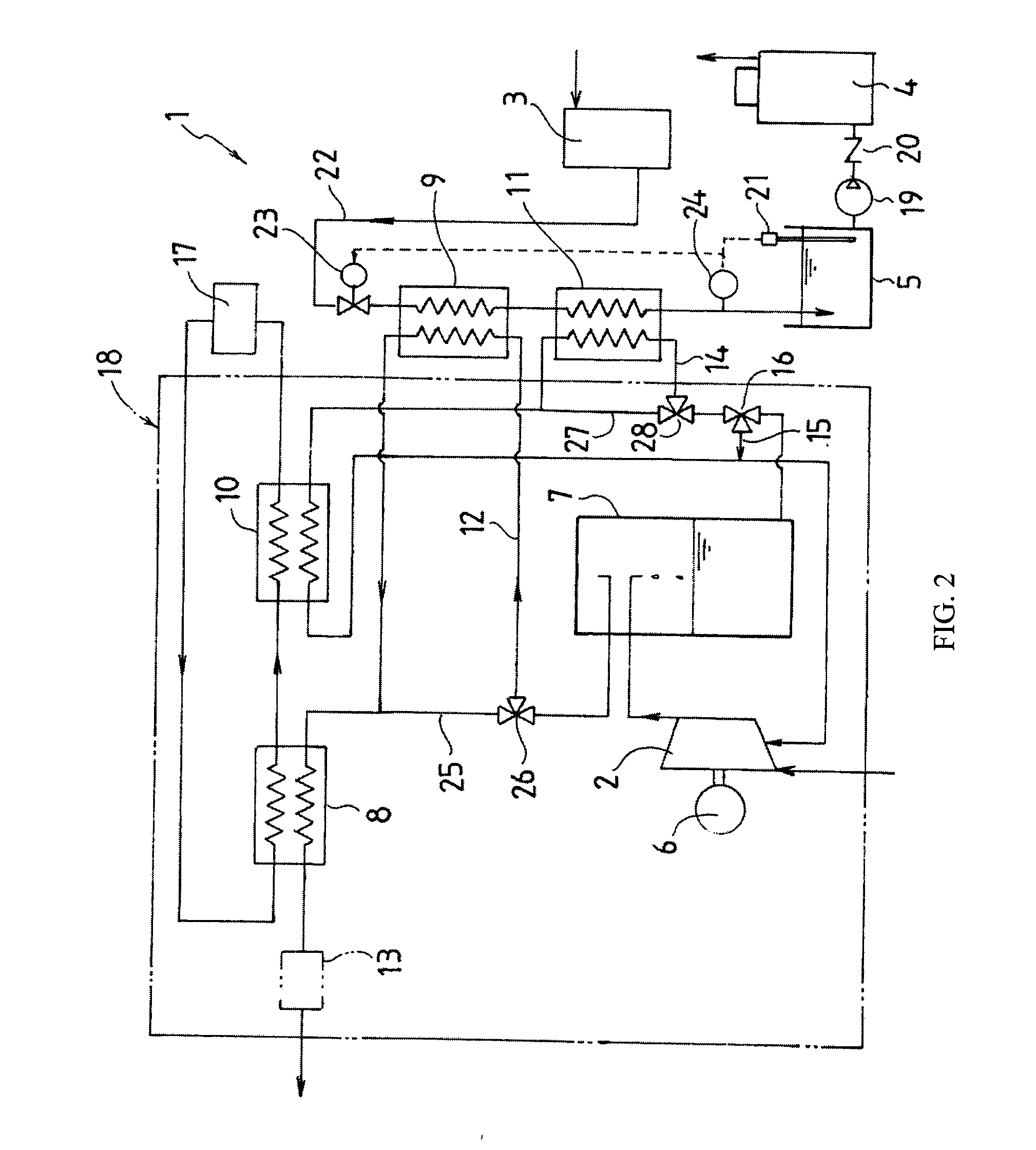
[0059]FIG. 3 is a view schematically showing a heat recovery system 1 in a third preferred embodiment according to the present invention and showing only differences from the first and second preferred embodiments.
[0060]The heat recovery system 1 in the third preferred embodiment also is basically similar to the heat recovery system 1 in the first and second preferred embodiments. Hence, a description will be mainly given of differences between the third preferred embodiment and the first and second preferred embodiments. The same component parts are designated by the same reference numerals.
[0061]In the first and second preferred embodiments, the second air cooler 9 and the second oil cooler 11 are connected in series to each other such that the water flows in order to the feedwater tank 5. In contrast, in the present third preferred embodiment, the second air cooler 9 and the second oil cooler 11 are connected in parallel to each other such that water to the feedwater tank 5 is br...
PUM
 Abstract
Description
Claims
Application Information