Eureka AIR delivers breakthrough ideas for toughest innovation challenges, trusted by R&D personnel around the world.

Damper for direct vent fireplace insert

Active Publication Date: 2012-04-19
MILES INDS
View PDF34 Cites 2 Cited by
  • Summary
  • Abstract
  • Description
  • Claims
  • Application Information

AI Technical Summary

Benefits of technology

[0012]In one aspect, the invention comprises a method and apparatus to control the air flow into a direct vent sealed fireplace, in which the air flow through the firebox is minimized when the fireplace is cold, namely at initial ignition. The air flow is then restricted as the temperature increases. This arrangement provides sufficient air flow at ignition to prevent starvation of the ignition system, but minimizes the loss of heated air once the firebox is in full operation.

Problems solved by technology

One problem in the management of air flow of direct vent gas fireplaces is to ensure that a sufficient amount of combustion air is available during ignition of the fireplace while avoiding inefficiencies due to the loss of heated combustion products during operation of the fireplace.
However, such restriction poses a corresponding problem during start-up when the air in the intake and exhaust vents is cool and stagnant.
The failure to do so may result in lift-off of the flame and the ignition of pockets of built up gas, or in starving the ignition system of combustion air and a failure to maintain ignition.
The solution is nonetheless inefficient.
However, when the combustion chamber is cold, there is not a sufficient supply of hot exhaust gases to produce or induce a draw from the primary air duct.
While this approach may assist in maintaining ignition, it still suffers the drawback of significant heat losses during continued operation of the fireplace because it is not intended to control overall air flow through the fireplace.
In sealed combustion gas fireplace systems, the problem of ignition air volume is sometimes addressed by maintaining a standing pilot flame that generates a small amount of air flow through the fire box and venting system.
However in some jurisdictions, the use of a standing pilot flame is falling out of favour with regulatory authorities because of perceived energy conservation reasons.
As the standing pilot has almost universally been used to ensure air flow through the firebox and duct system in colder climates, the absence of a standing pilot creates a challenge to reliable ignition of the burner.
The controller is hard-wired into the electric lines of the building in which it is installed, which may make the system difficult to install or retrofit.
This does not assist in ensuring that there is a sufficient air supply at ignition of the fireplace burners.
This should allow enough air to flow to successfully ignite the fireplace, but the circuitry and signalling required in this system is relatively complex.
Further, in this system, the damper remains open during the burner operation and is only intended to close the flue system in the off cycle.

Method used


Image

  • Damper for direct vent fireplace insert
  • Damper for direct vent fireplace insert
  • Damper for direct vent fireplace insert

Examples


Embodiment Construction

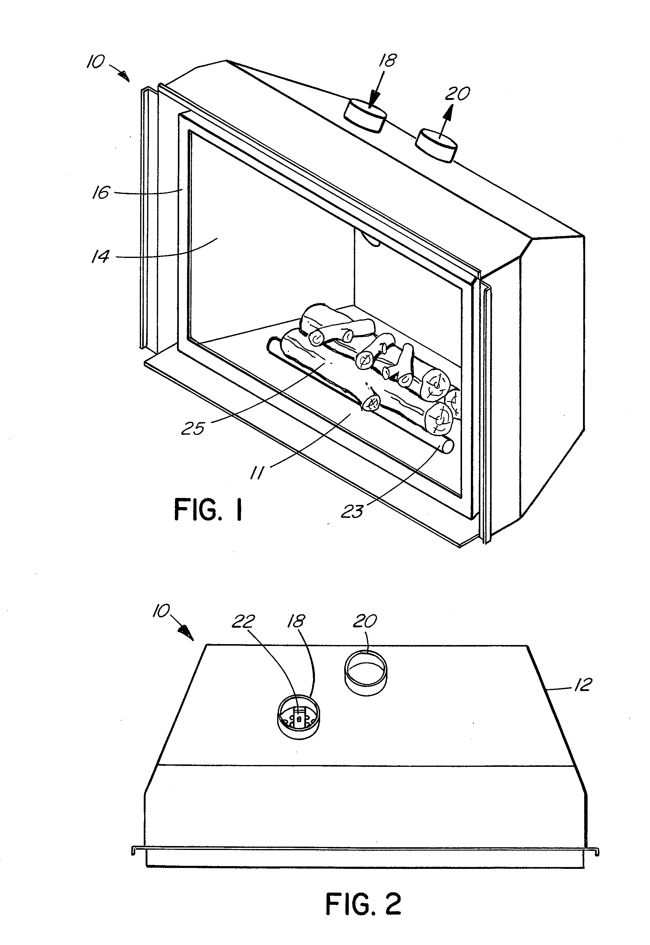
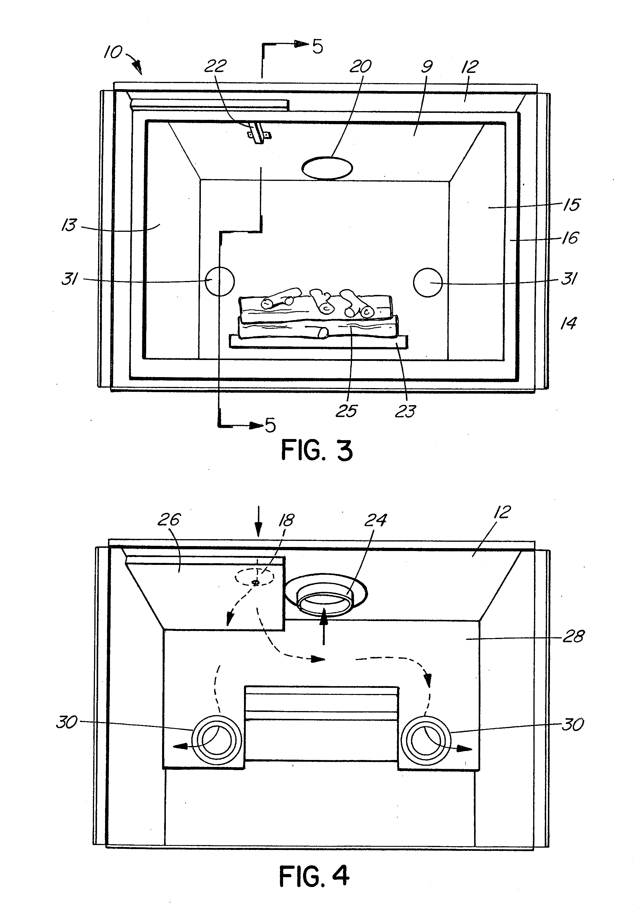
[0033]Referring to FIGS. 1-3, a sealed direct vent gas fireplace 10 includes an outer shroud 12 surrounding a firebox 14. A glass panel 16 seals the firebox 14 from the air inside the room in which the fireplace is located. Fireplace 10 also includes burner 23 and logset 25 within the firebox. It will be understood that certain elements such as false walls, baffles and various cosmetic elements are omitted from the drawings for clarity, but may or may not be included in a fireplace 10 comprising the invention described herein.

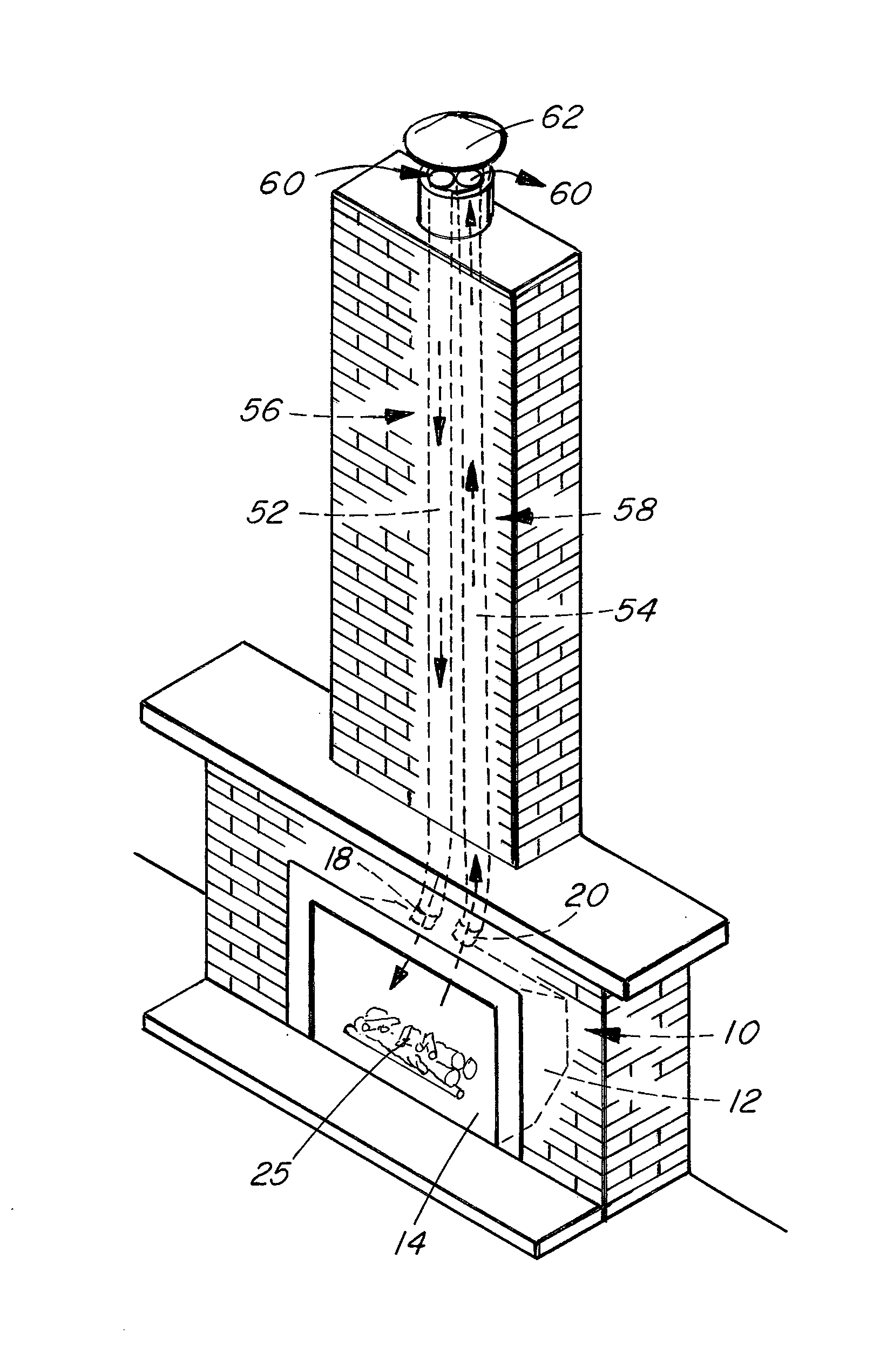
[0034]Combustion air is supplied to the fireplace by means of an air inlet 18 and gas combustion products are vented through exhaust outlet 20. As best seen in FIG. 9, during installation of the fireplace in a building, air inlet 18 is connected to an intake duct 52 to allow combustion air from outside the building to be drawn into the fireplace and the firebox 14. Similarly, exhaust outlet 20 is connected to an exhaust duct 54 for exhausting gas combustion pro...


PUM


Abstract

A damper mechanism restricting combustion and exhaust air flow in response to temperature changes in a direct vent sealed combustion gas fireplace is provided. The mechanism allows the fireplace to have unrestricted air flow when the fireplace is not on and to restrict the air flow when the fireplace is on. A bi-metallic temperature responsive element is used to move a restrictor element to restrict air flow allowing maximum air displacement during cold ignition and enhancing operating efficiency when the fireplace is on.

Description

FIELD OF THE INVENTION[0001]This invention relates to direct vent, sealed combustion gas fireplaces. In particular, this invention is directed to a method and apparatus for controlling the air flow to enhance the operating efficiency of a direct vent, sealed combustion gas fireplace while accommodating the need for a relatively unrestricted air supply during ignition in a fireplace.BACKGROUND OF THE INVENTION[0002]Unlike open flue wood or gas fireplaces that draw combustion air from the room in which they are located, the fireboxes of direct vent gas fireplaces are sealed from the room air. The fireplaces draw combustion air into the firebox from outside the building through air intake ducts and exhaust the combustion gases from the firebox out of the building through exhaust ducts. Air flow through the firebox and the ducting systems during operation of direct vent gas fireplaces is typically driven by thermal convection and the buoyancy of the combustion products. Relatively cool ...

Claims


Application Information

Patent Timeline
IPC IPC(8): F24B1/189
CPCF23N3/04F23L13/00F23J2211/10F24B1/1895F24C3/006F24C15/002
Inventor MILES, MARTINBOOK, BYRON
Owner MILES INDS
Why Eureka
Eureka Blog
Learn More