Power float

a technology of power floats and floats, which is applied in the direction of pv power plants, transportation and packaging, lighting and heating apparatus, etc., to achieve the effect of optimizing the stability of arrays, maximizing the stability and longevity of materials

Inactive Publication Date: 2012-04-19
WATER INNOVATIONS POWER & TECH HLDG
View PDF2 Cites 24 Cited by
  • Summary
  • Abstract
  • Description
  • Claims
  • Application Information

AI Technical Summary

Benefits of technology

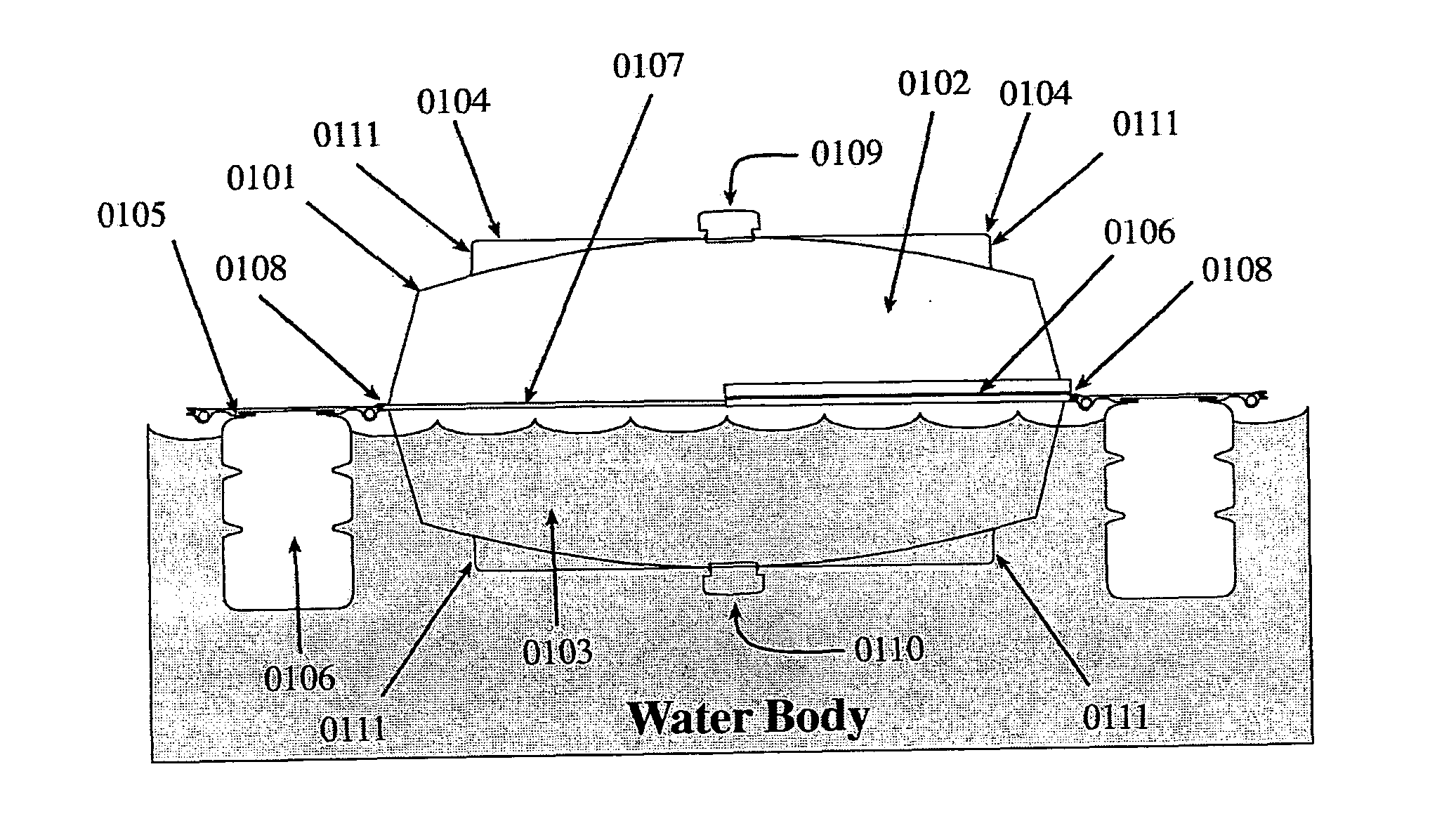
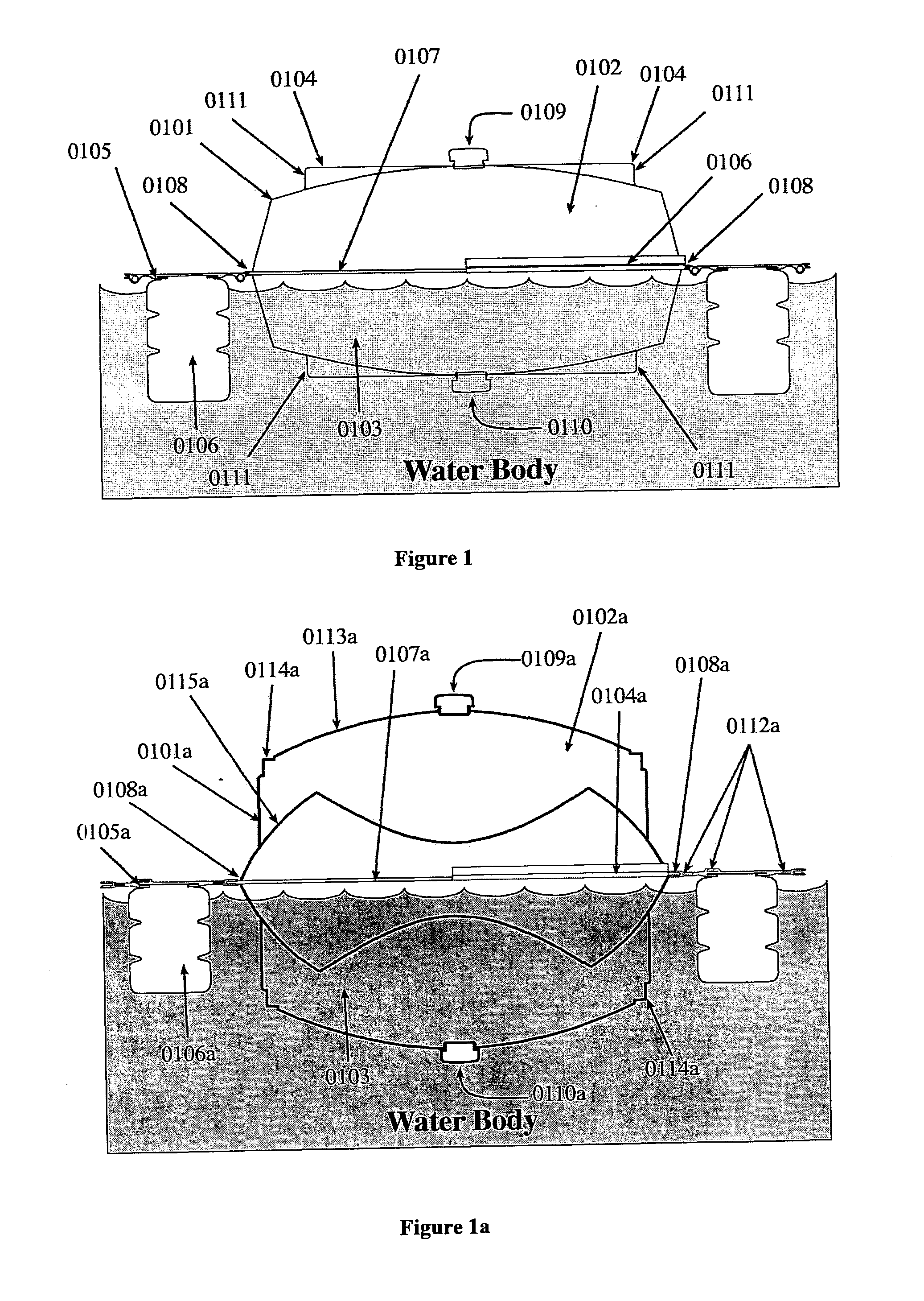
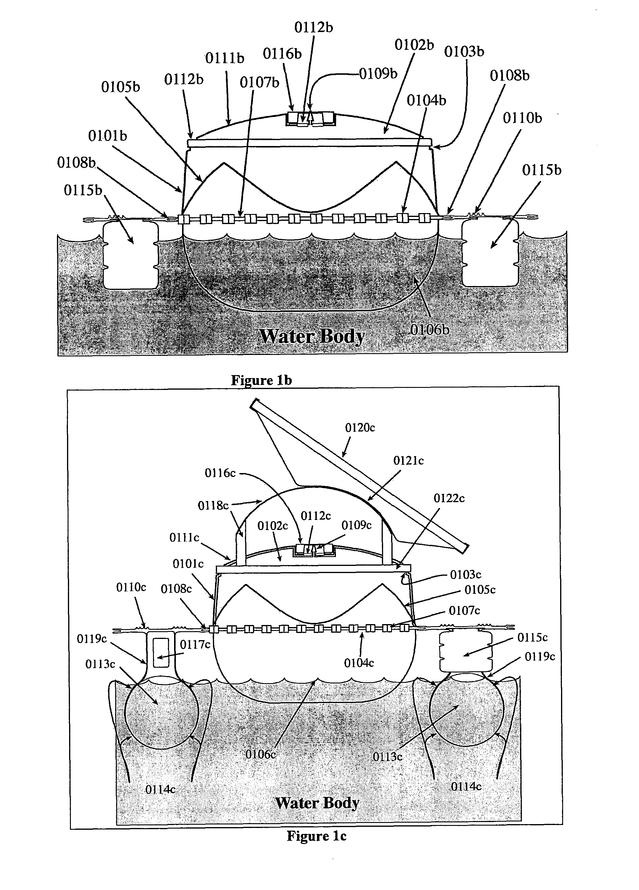
[0021]Lockable edge connectors are preferably incorporated in the edges of the modular shells. Preferably each shell incorporates a hole to allow air and / or water to move in and out of the formed module. The chains of modules may be connected together using chain connectors that also incorporate electrical conductors. Preferably at least some of the modules are flotation modules to ensure that the arrays are stable on the water surface. The flotation modules allow water to be held as ballast in the bottom half of the module. Additional flotation devices and ballast devices may also be used with the arrays to optimise the stability of the arrays in all weather conditions.
[0097]h) Multiple clusters can be automatically linked [via PLC control] during low light [low power] events to lower power generators, expanding diurnal power production duration;

Problems solved by technology

These prior art devices are restricted by:No facility for technology adaption to large / unlimited scale payload carrying capacity and thereforeNo utility level power generation capability;Containment problems on large gated deployments in the event of a Possible Maximum Storm [PMS] with storage level changes, major current changes and trash flow;Wind stability issues on large deployments due to insufficient product deployment strength, shear strength, integrity and ineffective active mooring strategies;Water quality issues via the action(s) of the elements [e.g.: long durations of prevailing winds constraining the product to small areas of the storage];Inability of the product to be clustered / contained in groups / area or moved without the use of booms;Inability to be moved in controlled orientation;No embedded power conducting capability;

Method used


Image

  • Power float
  • Power float
  • Power float

Examples


first embodiment

[0139]FIG. 14a illustrates the Access Module top view. The access module provides servicing and repair access to key parts of the system deployed on the water body;

[0140]FIG. 14b illustrates a sectional view of the said access module;

second embodiment

[0141]FIG. 14c illustrates a top view of the access module;

[0142]FIG. 14d illustrates a explosion diagram view of the said second embodiment;

[0143]FIG. 14e illustrates the access module and its use in deployment;

[0144]FIG. 14f illustrates a terminal bridge across a gutter between modules with the balloon floatation embodiment. The figure illustrates the use of the gutter pipe and its contents [if any], with the water in the gutter as a ballast [weight], for the deployment;

[0145]FIG. 15 illustrates two 9×2 clusters connected back to back to the terminal connector with an attached hinged gantry;

[0146]FIG. 16 illustrates several circular module clusters pivoted on a central axis with controlled tethering;

[0147]FIG. 17 illustrates the chain connector and module chaining lock with tethering inserts;

[0148]FIG. 18 illustrates a 10×10 module array with tethering allowing controlled movement of the array over the water body;

[0149]FIG. 19 illustrates a sectional view of the light extinction c...


PUM


Abstract

A modular floating impermeable rectangular module, with a connective clustering and solar collector carrying capability. The modular configuration is applied to a water surface, in a synergetic combination for the solar generation of power and the prevention of evaporation and / or airborne water and particulate contamination of the water body. Each module is adapted to support a solar collection panel for converting solar energy into electrical energy in which each flotation module is formed from two half shells which connect together to form a module, the outer surfaces of at least one shell being adapted to support a solar collector and each module is adapted on two opposed edge sections for connection in line to form a chain of modules and each solar collector in said chain being connected in electrical series and each chain of modules being connectable laterally to form arrays of modules and each chain of solar collectors being electrically connected in parallel.

Description

[0001]This invention relates to a device adapted to ameliorate evaporation of water storages and provide a platform for the solar generation of power.BACKGROUND TO THE INVENTION[0002]For some time there has been interest in the covering of water storages to reduce evaporation and to control air and water borne particulate contamination from those storages.[0003]WO 98 / 12392 discloses a flat polygonal floating body where the faces of the floating body have partly submerged vertical walls with lateral edges. The Device has an arched cover with a hole in the top cover for air exchange.[0004]Australian patent 199964460 discloses a modular floating cover to prevent loss of water from large water storages comprising modular units joined together by straps or ties, manufactured from impermeable polypropylene multi-filament, material welded together to form a sheet with sleeves. The sleeves are filled with polystyrene or polyurethane floatation devices to provide flotation and stiffness to t...

Claims


Application Information

Patent Timeline
Patent Type & Authority Applications(United States)
IPC IPC(8): H01L31/048B65D88/36
CPCB63B35/38B63B2035/4453F24J2/5267F24J2/542Y02E10/47H02S20/00Y02E10/50F24S30/452F24S20/70
Inventor CAP, GEORGE JAROSLAVWOODFIELD, ROSS
Owner WATER INNOVATIONS POWER & TECH HLDG
Why Eureka
Try Eureka