Metal core substrate

a core substrate and metal technology, applied in the direction of high current circuit adaptation, circuit bendability/stretchability, metallic pattern materials, etc., can solve the problems of increasing the number of parts, and consuming energy, so as to reduce the forming force

Active Publication Date: 2012-04-19
YAZAKI CORP
View PDF4 Cites 8 Cited by
  • Summary
  • Abstract
  • Description
  • Claims
  • Application Information

AI Technical Summary

Benefits of technology

[0012]It is therefore an object of the present invention to provide a metal core substrate capable of reducing the number of parts and coping with a high current specification.
[0016]In addition, when the common metal core material for two routing members is divided into a plurality of parts in the width direction of the metal core material, it is possible to reduce the forming force at the time of bending processing and to cope with a case where a plurality of power supply systems is provided.

Problems solved by technology

However, regarding a case where it is required to form a power supply box 20 into an unordinary polyhedral shape which is bent at a right angle due to vehicle mount requirements, as shown in FIG. 8, when routing members 100, 110 are accommodated in the power supply box 20, a problem is caused regarding the supply of the power supply energy to the downstream routing member 110.
However, in recent years, it is difficult to secure the mount space of the wire harness or the power supply box, the pressing need is to reduce the number of parts, and the upstream circuit requires a high current specification in the power supply box.
Accordingly, it is difficult to branch a thick electric wire by using the above branch connection.
The connector connection also has the same problems as the branch connection.
In other words, in recent years, it is difficult to secure the mount position of the wire harness or the power supply box, the pressing need is to reduce the number of parts, and the upstream circuit requires a high current specification in the power supply box.
Accordingly, it is difficult to set up a large-scaled connector by using the above connector connection.
However, since the upstream circuit in the power supply box requires the high current specification, it is not possible to cope with the high current by using the flexible printed substrate.
In addition, since the insulation layer and the copper foil are not formed on the third area of the one sheet of the metal core material, the metal core substrate can be bent at the third area and thus accommodated in the power supply box having an unordinary shape.

Method used


Image

  • Metal core substrate
  • Metal core substrate
  • Metal core substrate

Examples


Embodiment Construction

[0029]Hereinafter, illustrative embodiments of the present invention will be described with reference to the accompanying drawings.

Metal Core Substrate According To First Illustrative Embodiment

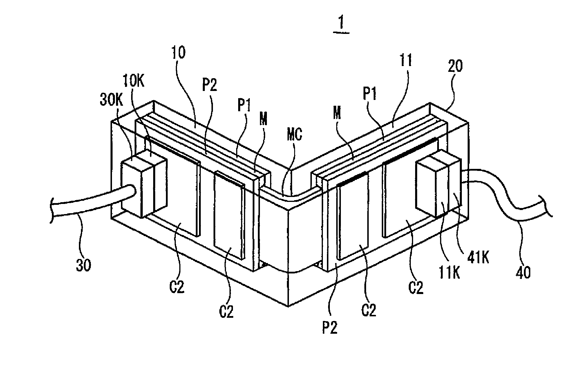
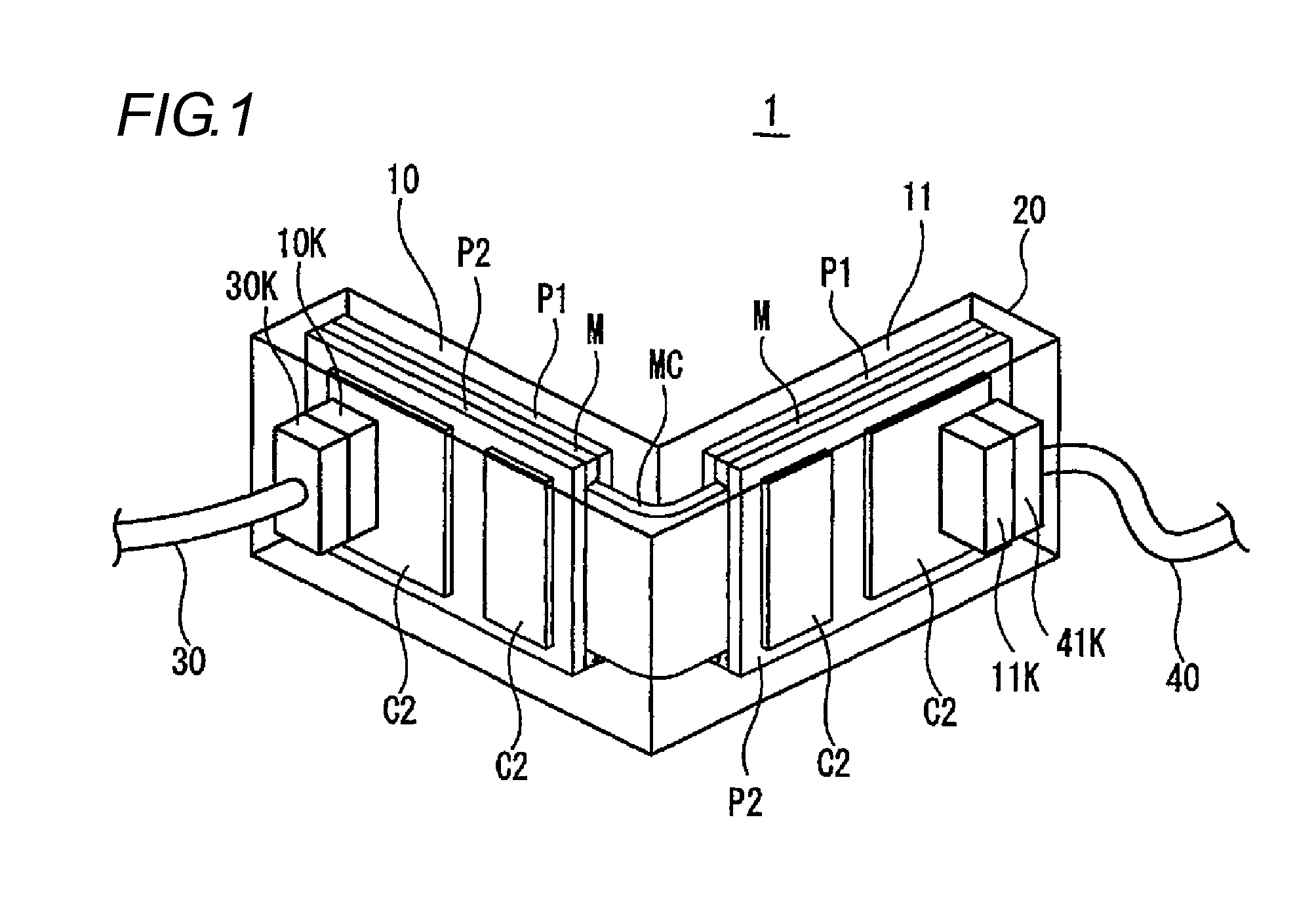
[0030]FIG. 1 is a perspective view showing a metal core substrate according to an illustrative embodiment of the present invention.

[0031]A metal core substrate 1 according to the illustrative embodiment of the present invention is configured so that routing members can be respectively accommodated in a power supply box having an unordinary shape. A routing member 10 and a routing member 11, which are mounted to a common metal core material M, are accommodated with being bent at a right angle in a power supply box 20 having an unordinary shape and a routing member accommodating space which is bent at a right angle, as shown in FIG. 1.

[0032]In FIG. 1, the reference numeral 1 indicates the metal core substrate having a plurality of routing members 10, 11 mounted thereto according to the illustr...


PUM

PropertyMeasurementUnit
angleaaaaaaaaaa
areaaaaaaaaaaa
widthaaaaaaaaaa

Abstract

A metal core substrate is provided. A first routing member is comprised of a first area of one sheet of metal core material; a first insulation layer formed on the first area; and a first circuit pattern made of a copper foil and formed on the first insulation layer. A second routing member comprised of: a second area of the one sheet of the metal core material, which is separated from the first area; a second insulation layer formed on the second area; and a second circuit pattern made of a copper foil and formed on the second insulation layer. A connecting member electrically connects the first routing member and the second routing member. The connecting member is comprised of a third area of the one sheet of the metal core material, which is interposed between the first area and the second area.

Description

BACKGROUND[0001]The present invention relates to a metal core substrate, and more particularly, to an electrical connection between routing members accommodated in a power supply box having an unordinary polyhedral shape which is bent at a right angle, rather than a power supply box having an ordinary planar shape.Example of Routing Member According To Related Art [0002]FIG. 7 is a cross sectional view illustrating an example of a routing member 80 according to the related art.[0003]In the routing member 80, conductive circuit patterns 82 are formed on upper and lower surfaces of an insulating substrate 81. The insulating substrate 81 is mounted with a semiconductor switching device (heat generating device) TR for switching and controlling load, a driving member DR for driving the semiconductor switching device TR, a heat radiation fin F for the semiconductor switching device TR and a connector C. The routing member 80 is supplied with power from a vehicle-mounted battery through a ...

Claims


Application Information

Patent Timeline
Patent Type & Authority Applications(United States)
IPC IPC(8): H05K1/09
CPCH05K1/05H05K1/0278H05K1/0263
Inventor SUGIURA, TOMOHIROHARAO, AKIRAKUBOTA, MINORU
Owner YAZAKI CORP
Why Eureka
Try Eureka