Methods and apparatus for treating water and wastewater employing a cloth disk filter

Active Publication Date: 2012-04-19
ALFA LAVAL ASHBROOK SIMON HARTELY INC
View PDF28 Cites 50 Cited by
  • Summary
  • Abstract
  • Description
  • Claims
  • Application Information

AI Technical Summary

Benefits of technology

[0044]When filtration headloss reaches a filtration termination set point, a backwash flow control valve opens. Then the backwash arm(s) move vertically, sweeping the filter cloth surface from the bottom to top (or alternatively from top to bottom). In apparatus within this embodiment, the backwash arm is driven by a drive assembly, which is located on the top of filter. In certain embodiments, the drive assembly comprises a drive frame weldment which supports a drive motor, a drive shaft, a miter gear box, lifting screw jacks, and ancillary mechanisms (such as the aforementioned vertical backwash arm guide members) to impart the vertical cleaning (backwash) motion. In certain embodiments, the backwash arm travel stop is controlled by a proximity switch, for example an infrared proximity switch, or other acceptable motion controller. Certain embodiments comprise a backwash pump fluidly connected to the backwash header. In certain embodiments, th

Problems solved by technology

One of the main disadvantages of the cloth disk filter is the nature of the cloth disk filtration-surface filtration.
In those applications, usually the cloth filter disk shows very short filter run and frequent backwash.
In embodiments using square-shaped filter cassettes, because the rotating backwash arm cleans a circle area of the square shaped filter cloth surface, a significant (approximately 22.5%) of the square filter cloth area remains fouled and unavailable for filtration.
It is not only a waste of filtration area but also has negative affect on filter effluent quality and aesthetics of the process.
Another option presently practiced is to use a more expensive and difficult to fabricate circular disk filter cas

Method used


Image

  • Methods and apparatus for treating water and wastewater employing a cloth disk filter
  • Methods and apparatus for treating water and wastewater employing a cloth disk filter
  • Methods and apparatus for treating water and wastewater employing a cloth disk filter

Examples


embodiment 100

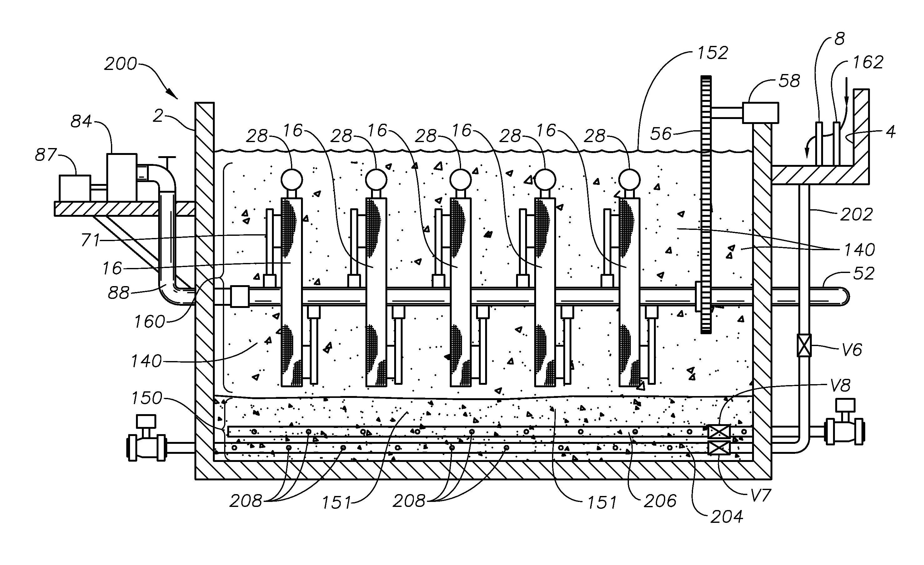
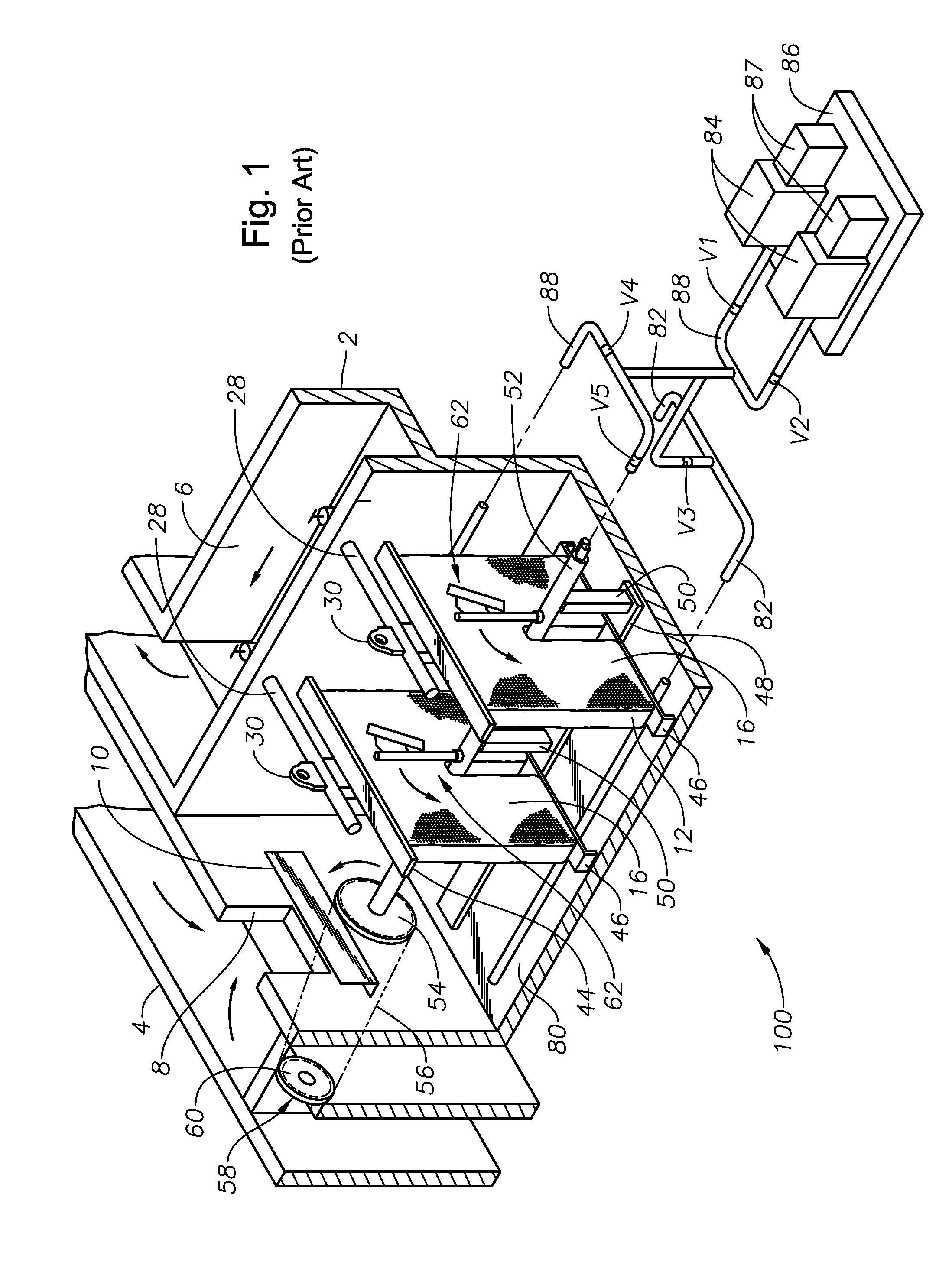
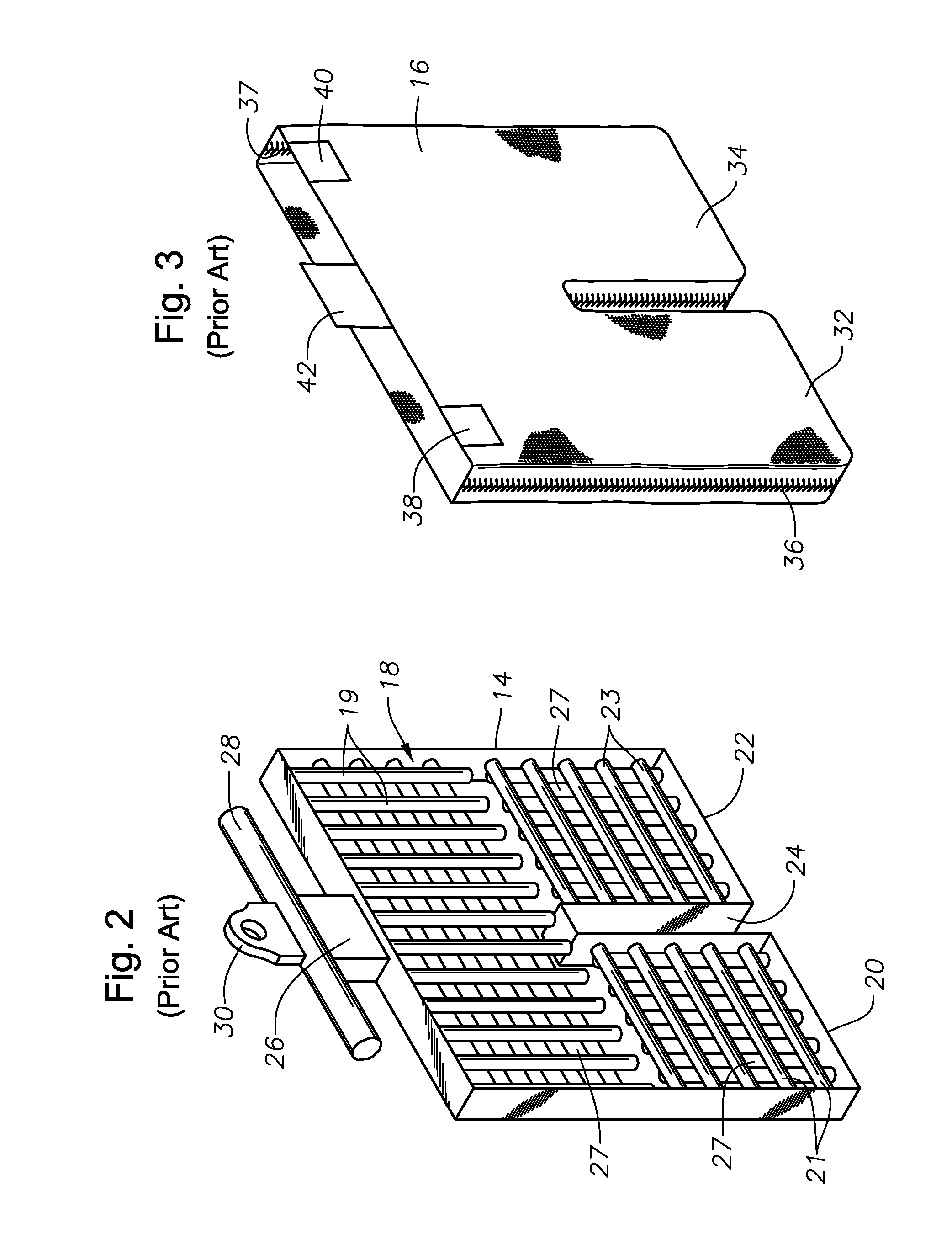
[0057]For comparison purposes, FIGS. 1-4 illustrate schematically a prior art cloth disk filter embodiment 100, which was described previously in the background section. As indicated previously, prior art embodiment 100 does not include facilities allowing screened water or wastewater to flow upward through sludge blanket region 150 formed on the bottom of vessel 2, nor does it teach or suggest backwash assemblies comprising backwash arms that are able to clean substantially all of the filter cloth surface. As used herein, “substantially all of the filter cloth surface” means 90 percent, or 95 percent, or in certain embodiments, 100 percent of the filter cloth surface.

[0058]The inventors herein have conceived methods and apparatus utilizing a combination of a sludge blanket and a cloth disk filter, and have further conceived cloth disk filter apparatus and methods of using same wherein substantially all of the cloth filter surfaces are backwashed (with or without the sludge blanket ...

embodiment 600

[0063]FIG. 10 illustrates backwash arm 318 just beginning its movement upward along cassette 12 and dirty filter cloth 16. FIG. 11 illustrates backwash arm 318 almost finished making a sweep upwards. Note that filter cloth 16 behind (below) backwash arm 318 is now clean. As may be appreciated, substantially all of filter cloth 16 is cleaned using this apparatus and method. A backwash pump may not be required, nor are complicated rotation mechanisms. It will be understood that the backwash features of embodiment 600 may replace the backwash features illustrated in the prior art cloth disk filter embodiment illustrated in FIG. 1, and may be practiced without the sludge blanket feature described herein, in other words where influent enters the top of the vessel 2, as in the embodiments illustrated in FIG. 1.

[0064]FIG. 12 is a schematic cross-sectional view, and FIGS. 13 and 14 are schematic end elevation views, respectively, of another cloth disk filter embodiment 700 in accordance wit...


PUM

PropertyMeasurementUnit
Flow rateaaaaaaaaaa
Concentrationaaaaaaaaaa
Flexibilityaaaaaaaaaa

Abstract

Methods and apparatus for treating water and wastewater include the step of flowing a suspended solids stream generally upward through a sludge blanket region of a cloth disk filter vessel, thus forming a partially treated effluent composition and a solids-enriched sludge blanket. The partially treated effluent composition is allowed to flow generally upward to a cloth filter zone in the vessel after contacting the sludge blanket. The methods include flowing the suspended solids stream through one or more distribution headers positioned in the sludge blanket. An option is to provide a sludge concentration zone in the sludge blanket region, allowing sludge to flow into the sludge concentration zone to form concentrated sludge. Other methods and apparatus include backwash assemblies that backwash substantially the entire filter cassette surfaces, with or without use of a sludge blanket zone. Either the backwash assemblies or filter cassettes move in the latter methods and apparatus.

Description

BACKGROUND[0001]1. Field of the Disclosure[0002]The disclosure is generally related to the field of water and wastewater treatment. More specifically, the disclosure relates to novel apparatus and methods of using same which address problems of removal of solids and chemically-induced flocs from residential, municipal, and / or industrial wastewater.[0003]2. Description of Related Art[0004]A conventional method for reducing solids from residential, municipal, and industrial wastewater is by using a cloth disk filter. Cloth disk filters are gaining in popularity in municipal tertiary and industrial wastewater filtration because of their low capital cost, acceptable solids removal efficiency, low filtration headloss, low reject rate (little or no chemical treatment) and small footprint.[0005]A prior art cloth disk filter is illustrated schematically in FIG. 1, with parts cut away so that some of the key components may be better understood. The prior art cloth disk filter embodiment 100 ...

Claims


Application Information

Patent Timeline
IPC IPC(8): B01D37/00B01D29/68B01D36/00B01D29/50
CPCB01D29/39B01D29/41B01D2201/082B01D29/684B01D29/682
Inventor XIA, YONGMINGDEVINE, JEFFREY S.DANNEMANN, CHARLES G.
Owner ALFA LAVAL ASHBROOK SIMON HARTELY INC
Why Eureka
Try Eureka