Method, Donor eNB And Radio Relay System For Realizing Service Flows Transmission Of Mobile Terminal

a technology of radio relay system and mobile terminal, which is applied in the field of cellular wireless communication system, can solve the problems of poor communication quality, limited wireless coverage of fixed enb network, and inevitable leakage of wireless network coverag

Active Publication Date: 2012-04-19
ZTE CORP
View PDF3 Cites 39 Cited by
  • Summary
  • Abstract
  • Description
  • Claims
  • Application Information

AI Technical Summary

Benefits of technology

[0057]In the system which introduces the relay in the present invention, when using the relay as the entity to be scheduled, the QoS requirement of each service of UE of the relay is met.

Problems solved by technology

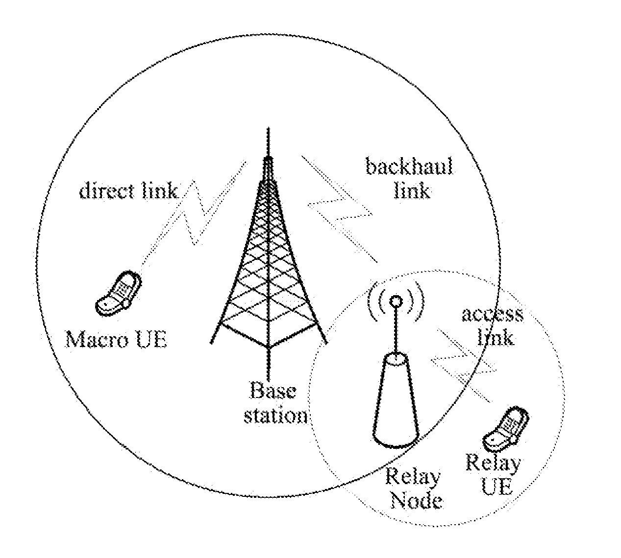
In cellular wireless communication system, the wireless coverage of fixed eNB network is limited because of various reasons, for example, various kinds of building constructions blocking the radio signal causes the inevitable coverage leak in the coverage of wireless network.
In addition, in the marginal area of a cell, the weakening of radio signal intensity and the interference of the neighboring cell result in the poor quality of communication and the increasing of the error rate of wireless transmission when the terminals are in the marginal area of the cell.

Method used


Image

  • Method, Donor eNB And Radio Relay System For Realizing Service Flows Transmission Of Mobile Terminal
  • Method, Donor eNB And Radio Relay System For Realizing Service Flows Transmission Of Mobile Terminal
  • Method, Donor eNB And Radio Relay System For Realizing Service Flows Transmission Of Mobile Terminal

Examples


embodiment one

[0080]the donor eNB allocates a logical channel for each service data flow of each UE of the relay station, makes the different service data flows of the UE correspond to the logical channels one by one, and the identifier of the logical channel is compounded by the UE identifier and the service identifier (i.e. UE ID+UE service ID). UE ID can be an internal ID used on a Un interface, the different UEs of the relay station have different IDs, for example, it can be the Cell Radio Network Temporary Identifier (C-RNTI) of the UE of the relay station, UE service ID represents the different services in a UE, for example, it can be EPS ID or E-RAB ID.

[0081]In the prior art, the maximum number of the logical channels of each UE corresponding to the eNB on Un interface is 16, in the present invention, through the identifier mode above, each logical channel corresponds to a service data flow, not simply the number of the logical channels is enlarged, but also the original single logical cha...

embodiment two

[0093]As shown in FIG. 15, in the PDCP module, the donor eNB maps one or more different service data flows with the quality of service requirement being in the identical quality of service scope to the identical logical channel, that is to say, a priority scheduling is performed for the service data flow of each UE, the scheduling is responsible for finishing the priority between the different services of different UEs, but it does not relate to the problem of allocating all physical resources for this service.

[0094]The quality of service scope is determined by the donor eNB, which can be made according to the various parameter values of QoS parameters, for example, QoS can be the same, or the rule that QCIs are identical in QoS maps multiple service data flows to the identical logical channel, to make the number of the logical channels on the follow-up MAC layer less than that in embodiment one so as to decrease processing amount of the following MAC layer scheduling / priority proce...


PUM


Abstract

A method, donor eNB and radio relay system for realizing service flow transmission of a terminal are disclosed in the present invention. Wherein a relay station is connected to the donor eNB through a backhaul link, and a scheme for transmitting the service data flow on the backhaul link is: the relay station and the donor eNB transmit each service data flow of each UE on a logical channel set by the donor eNB, thereby when the Relay is configured as a scheduled entity in a Un interface, the problem that the QoS requirement of each service of UE of the Relay can not be satisfied is resolved, so that when the Relay is configured to be a scheduled entity in a Un interface, the QoS requirement of each service of UE of the relay can be satisfied.

Description

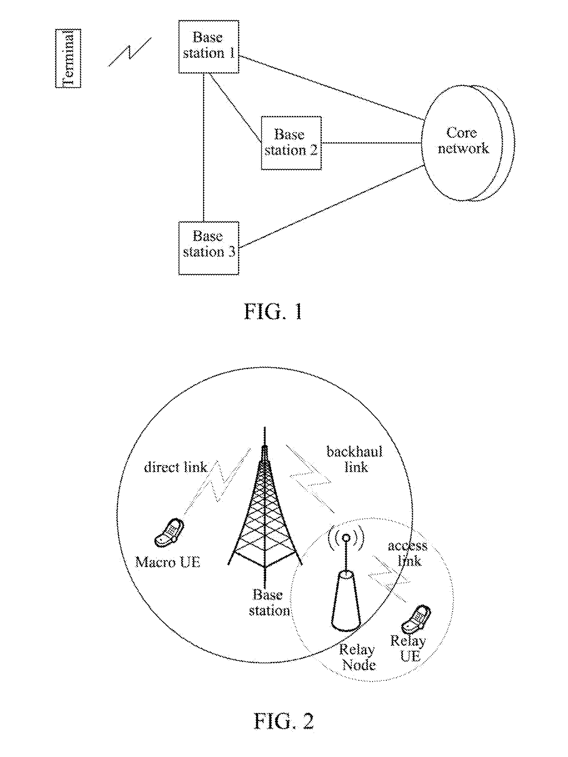
TECHNICAL FIELD[0001]The present invention relates to a cellular wireless communication system, especially to a method, donor eNB and radio relay system for realizing service flow transmission of a terminal.BACKGROUND OF THE RELATED ART[0002]As shown in FIG. 1, a cellular wireless communication system is mainly composed of Core Network (CN), Radio Access Network (RAN), and terminals. Core Network is responsible for non-access stratum transaction, for instance, the updating of the location of a terminal, and is the anchor of user plane. RAN comprises eNB, or eNB and eNB controller, and the RAN is responsible for access stratum transaction (for instance, the management of radio resources), there can be a physical and logical connection between eNBs, such as the connection between eNB 1 and eNB 2 or eNB 3 as shown in FIG. 1, and each eNB can connect to one or more CN nodes. The terminal, i.e. User Equipment (UE), refers to various equipments which can communicate with cellular wireless...

Claims


Application Information

Patent Timeline
Patent Type & Authority Applications(United States)
IPC IPC(8): H04W88/04H04W72/08H04W4/00
CPCH04B7/2606H04W4/00H04W88/08H04W84/047H04W80/02H04B7/15528
Inventor HUANG, YADALI, DAPENG
Owner ZTE CORP
Why Eureka
Try Eureka