Insertion section for laryngoscope with lateral tube guide

a technology of lateral tube guide and laryngoscope, which is applied in the field of insertion section of laryngoscope, can solve the problems of retained tube extending from the distal end, affecting the safety of insertion section, and not having guide tubes, so as to facilitate safe use and reduce the bulk of the insertion section

Inactive Publication Date: 2012-04-19
COVIDIEN AG
View PDF9 Cites 14 Cited by
  • Summary
  • Abstract
  • Description
  • Claims
  • Application Information

AI Technical Summary

Benefits of technology

[0011]As the endotracheal tube is retained in a plane, the endotracheal tube can be advanced in a distal direction, towards a patient's larynx, without lateral curvature, thereby reducing resistance to movement. Furthermore, the said plane of a retained endotracheal tube can readily be aligned with a patient's median plane, so that, once the laryngoscope insertion section has been introduced correctly into a patient's oral cavity and the larynx exposed, further manipulation of the orientation of the insertion section is unlikely to be required. In embodiments where the endotracheal tube is manually advanced, rather than advanced by automatic or semi-automatic means, the hand motion required to advance the endotracheal tube into the larynx is a natural movement, similar to the movement required to introduce an endotracheal tube using traditional laryngoscopes. Preferably, the tube guide is configured so that the retained endotracheal tube continues in said plane distally of the most distal location where a retained endotracheal tube contacts the insertion section.
[0024]The insertion section may comprise an elongate support member and a plurality of tube guiding members extending laterally from the elongate support member to contact the inferior or superior surface of a retained endotracheal tube. The elongate support member may be located in a plane parallel but spaced apart from the said plane. Preferably, the tube guiding members are arrange to leave exposed either the inferior or the superior surface of a retained endotracheal tube at least one location between the most proximal location where the insertion section contacts a retained endotracheal tube and the most distal location where the insertion section contacts a retained endotracheal tube. Preferably, there is at least one location between the most proximal location where the insertion section contacts a retained endotracheal tube and the most distal location where the insertion section contacts a retained endotracheal tube where both the inferior and superior surfaces of a retained endotracheal tube are left exposed. These arrangements minimise the bulk of the tube guide and thereby reduce the bulk of the insertion section, facilitating safe use of the insertion section in the confined space of a patient's oral cavity.
[0025]The tube guide may be arranged to retain an endotracheal tube under flexural tension continuously from the most proximal location where the insertion section contacts a retained endotracheal tube to the most distal location where the insertion section contacts a retained endotracheal tube. This can facilitate retention of the endotracheal tube by tube guiding members extending laterally from an elongate support member, reducing the number and / or bulk of tube guiding members.
[0028]The laryngoscope preferably comprises a light source. The elongate cavity may be operable to encompass the light source in use and the insertion section may comprise a translucent or transparent portion to enable light from the light source to be shone on a patient's larynx in use. Thus, the insertion section may function to protect the light source from contact with bodily fluids and / or air during use.

Problems solved by technology

However, they do not guide tubes as such.
A disadvantage of known video laryngoscope insertion sections with lateral tube guides relates to the orientation at which a retained tube extends from the distal end of the insertion section.
However, there are a number of disadvantages associated with this arrangement.
Secondly, the distal tip of the endotracheal tube appears to move both sideways and upwards simultaneously in the field of view of the image collector.
This can make it more difficult for a user to be confident that a retained endotracheal tube is being guided along the correct path to be inserted into the larynx.
Thirdly, in some patient's the larynx will be further anterior of the epiglottis than normal.
As a result, insertion of the endotracheal tube is made more difficult.

Method used


Image

  • Insertion section for laryngoscope with lateral tube guide
  • Insertion section for laryngoscope with lateral tube guide
  • Insertion section for laryngoscope with lateral tube guide

Examples


Embodiment Construction

[0047]An example embodiment of the invention will now be described with reference to an insertion section having one or more moveable tube guiding members. However, the invention is equally applicable to insertion sections having only fixed tube guiding members.

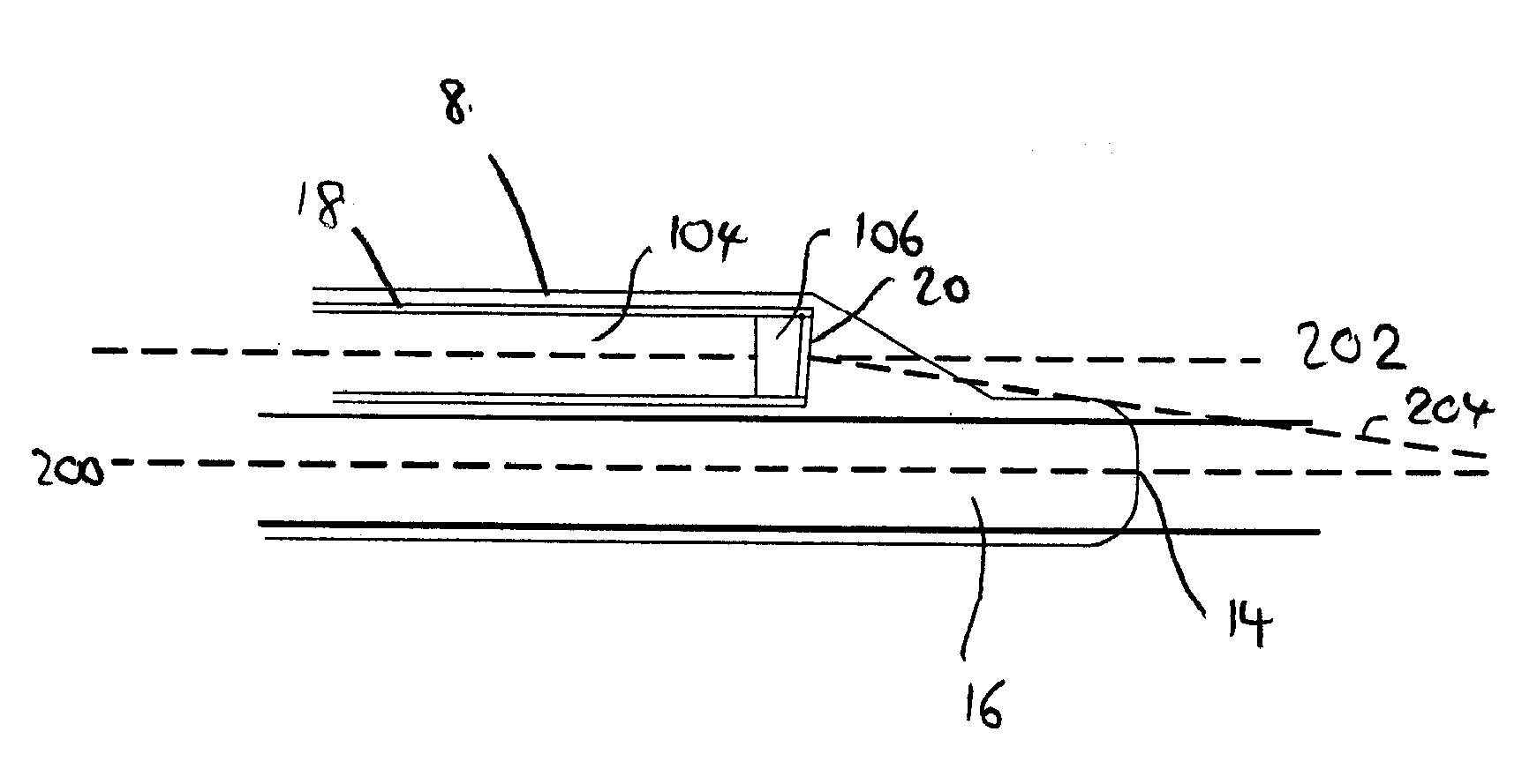
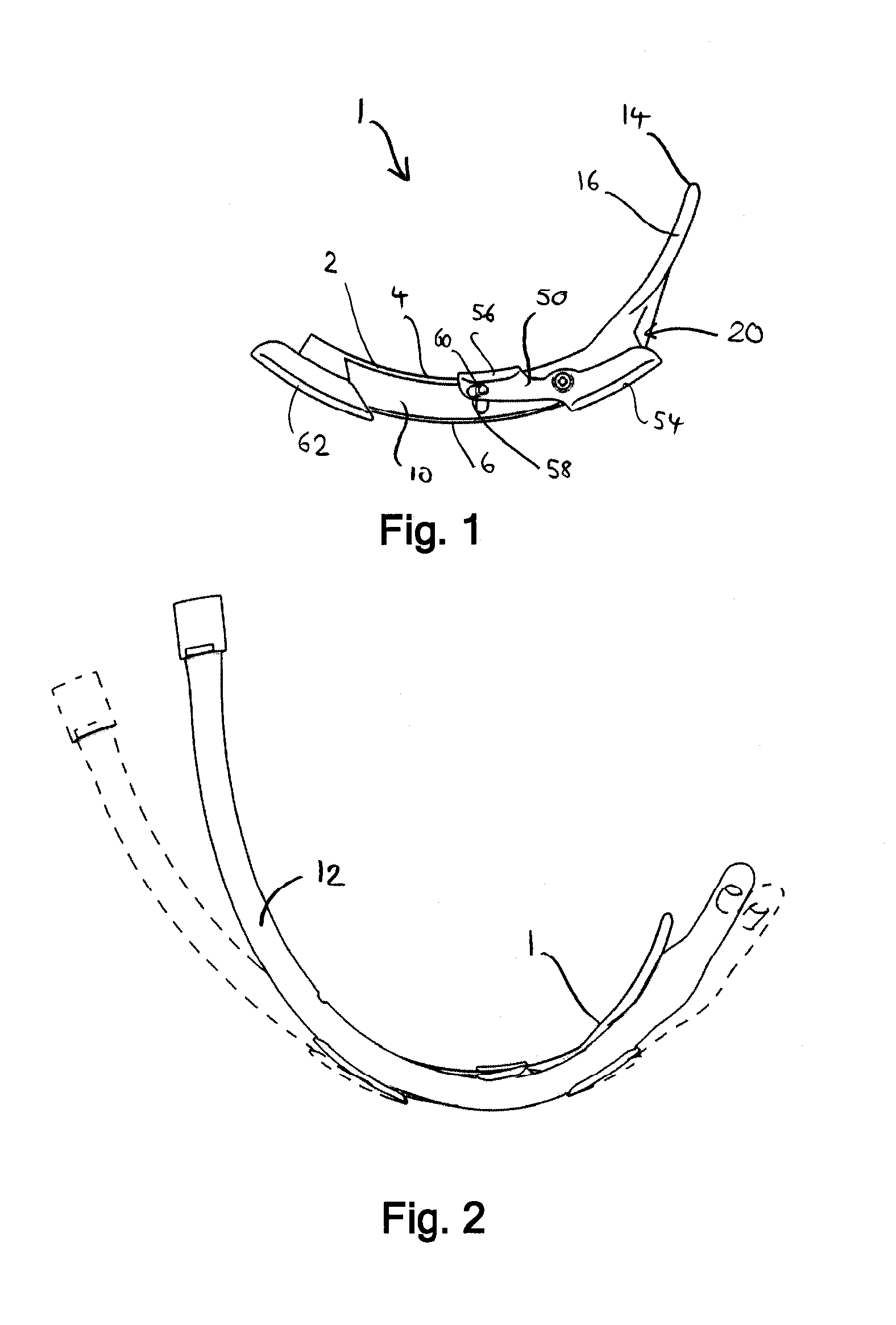
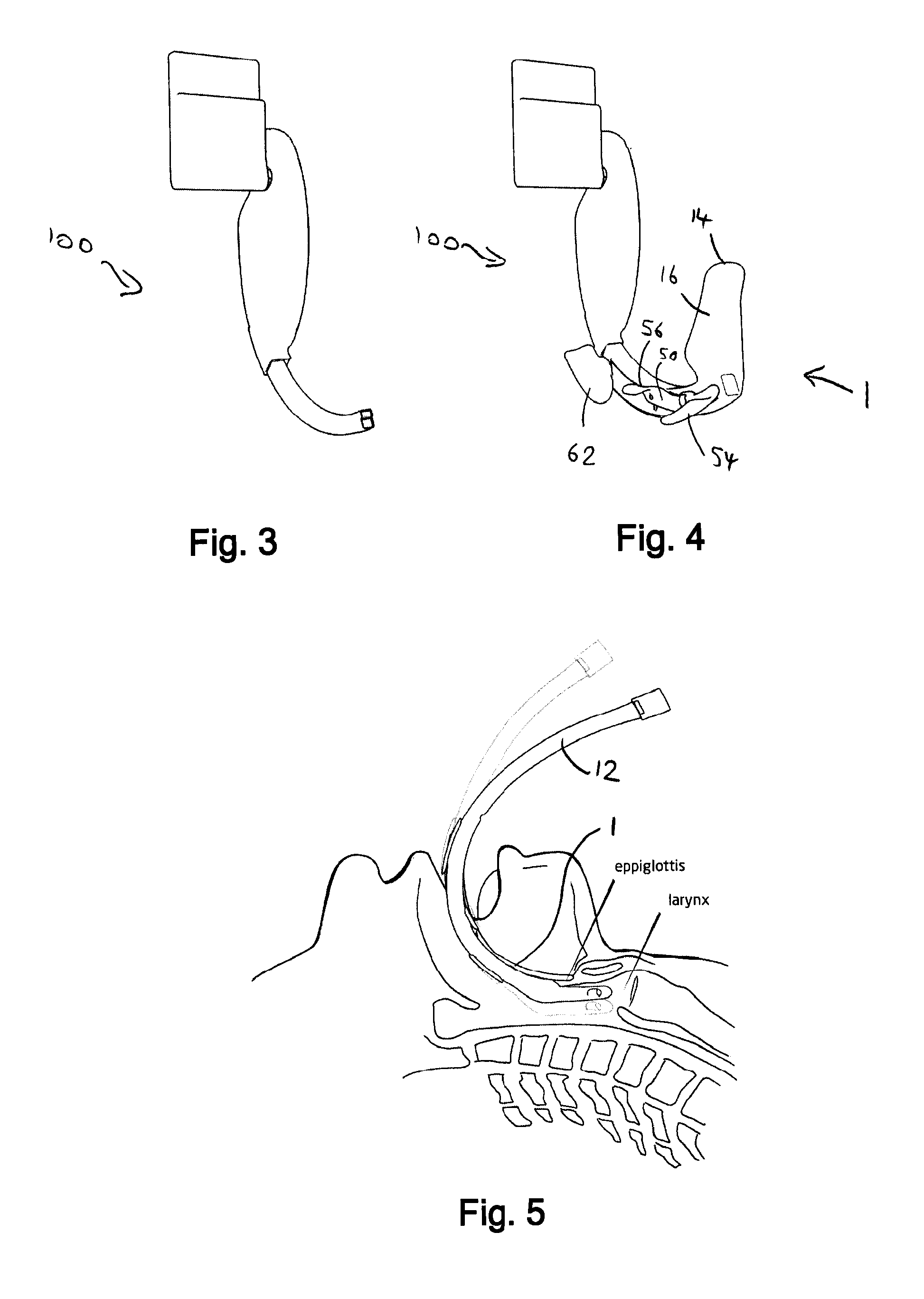
[0048]With reference to FIGS. 1 and 2, a laryngoscope insertion section, shown generally as 1, has a body 2, formed as a unitary moulding from a transparent plastics material. The body has a smooth inferior surface 4, which contacts a patient's palette in use, an opposing superior surface 6, a first smooth lateral surface 8 (at the rear in FIG. 1), and an opposing second lateral surface 10. The second lateral surface has a profile including a concave groove which runs along the majority of the length of the second lateral surface and which functions as part of a tube guide for an endotracheal tube 12. The insertion section has a distal end 14 comprising a spatulate member 16 which functions, in use, to lift a patient's anatom...


PUM


Abstract

A laryngoscope insertion section for a laryngoscope, which is typically a video laryngoscope, includes a lateral tube guide configured to retain an endotracheal tube in a plane. A viewing port for a camera or other image collector is laterally displaced from the plane of the endotracheal tube. The said plane of the endotracheal tube is aligned substantially in the same plane as a patients median plane and the tube can be advanced into the larynx using a natural curving motion similar to the motion used to introduce an endotracheal tube using a convention laryngoscope. In a preferred embodiment, the distal tip of the insertion section and a retained endotracheal tube will be located in the patients median plane during intubation. As the tube guide retains endotracheal tubes substantially in a plane, lateral curvature is avoided, reducing resistance to advancement of the tube.

Description

FIELD OF THE INVENTION[0001]The present invention relates to the field of insertion sections for laryngoscopes which include lateral tube guides for detachably retaining and guiding endotracheal tubes during intubation.BACKGROUND TO THE INVENTION[0002]Laryngoscopes are medical devices which are employed to introduce endotracheal tubes into patient's airways, for example, when a patient is being anaesthetised. Laryngoscopes comprise insertion sections, which are the part of a laryngoscope which extends towards and into a patient's oral cavity during intubation. Insertion sections may be removably attachable to a laryngoscope body, integral parts of laryngoscopes or themselves function as laryngoscopes. As well as an insertion section, laryngoscopes typically comprises a handle which is usually elongate and which may be arranged at an angle to the proximal end of the insertion section or generally parallel to the proximal end of the insertion section, or at any angle therebetween. Lar...

Claims


Application Information

Patent Timeline
Patent Type & Authority Applications(United States)
IPC IPC(8): A61B1/267A61M16/04
CPCA61M16/0488A61B1/267A61B1/07A61B1/044A61B1/06A61B1/00032A61B1/00052A61B1/00087A61B1/00105
Inventor MCGRATH, MATTHEW J.R.WALKER, MORGAN JAMES
Owner COVIDIEN AG
Why Eureka
Try Eureka