Automatic Control of Driveline States

a technology of automatic control and driveline, applied in the direction of instruments, transportation and packaging, tractors, etc., can solve the problems of reducing inconvenience for operators, and the awd system tends to reduce the fuel economy of operators, so as to reduce the disruption of the operation, reduce the disruption, and improve the fuel economy

a technology of automatic control and driveline, applied in the direction of instruments, transportation and packaging, tractors, etc., can solve the problems of reducing inconvenience for operators, and the awd system tends to reduce the fuel economy of operators, so as to reduce the disruption of the operation, reduce the disruption, and improve the fuel economy

US20120095659A1Inactive Publication Date: 2012-04-19FORD GLOBAL TECH LLC

Image

  • Automatic Control of Driveline States
  • Automatic Control of Driveline States
  • Automatic Control of Driveline States

Examples


Embodiment Construction

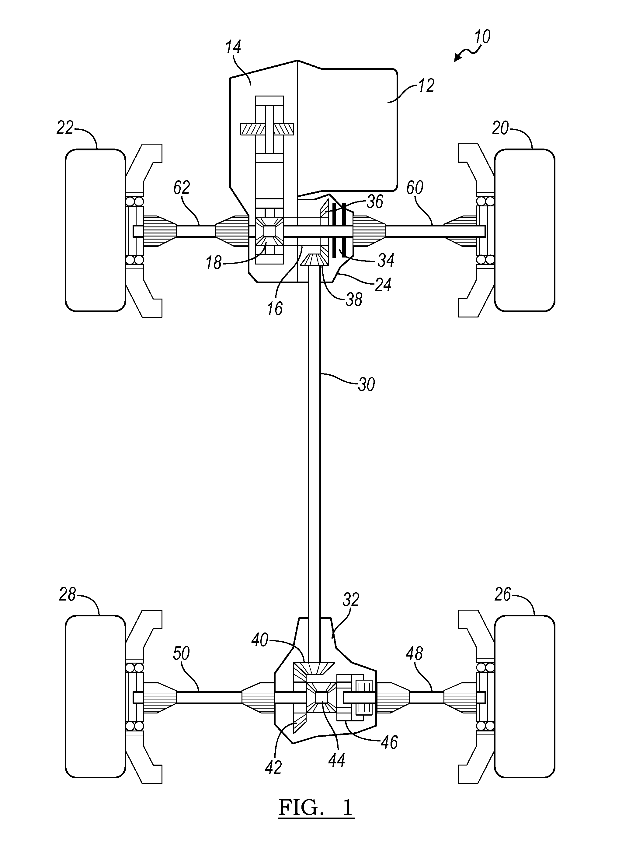
[0015]The driveline 10 of FIG. 1 includes a power source 12, such as an internal combustion engine or an electric motor, and a transmission 14 that produces a variable ratio between the speed of its output 16, which is continually driveably connected through a differential mechanism 18 to the primary road wheels 20, 22, and the speed of the transmission input, which is driveably connected to the power source.

[0016]The primary wheels 20, 22 are driven continually by the engine during torque transfer conditions. The secondary wheels 26, 28 are undriven road wheels, except that they are driven by the engine during torque transfer conditions when AWD is operating.

[0017]A power transfer unit (PTU) 24 transmits power from the transmission output 16 selectively to the secondary road wheels 26, 28. A driveshaft 30 transmits rotating power from the PTU 24 to a rear drive unit (RDU) 32.

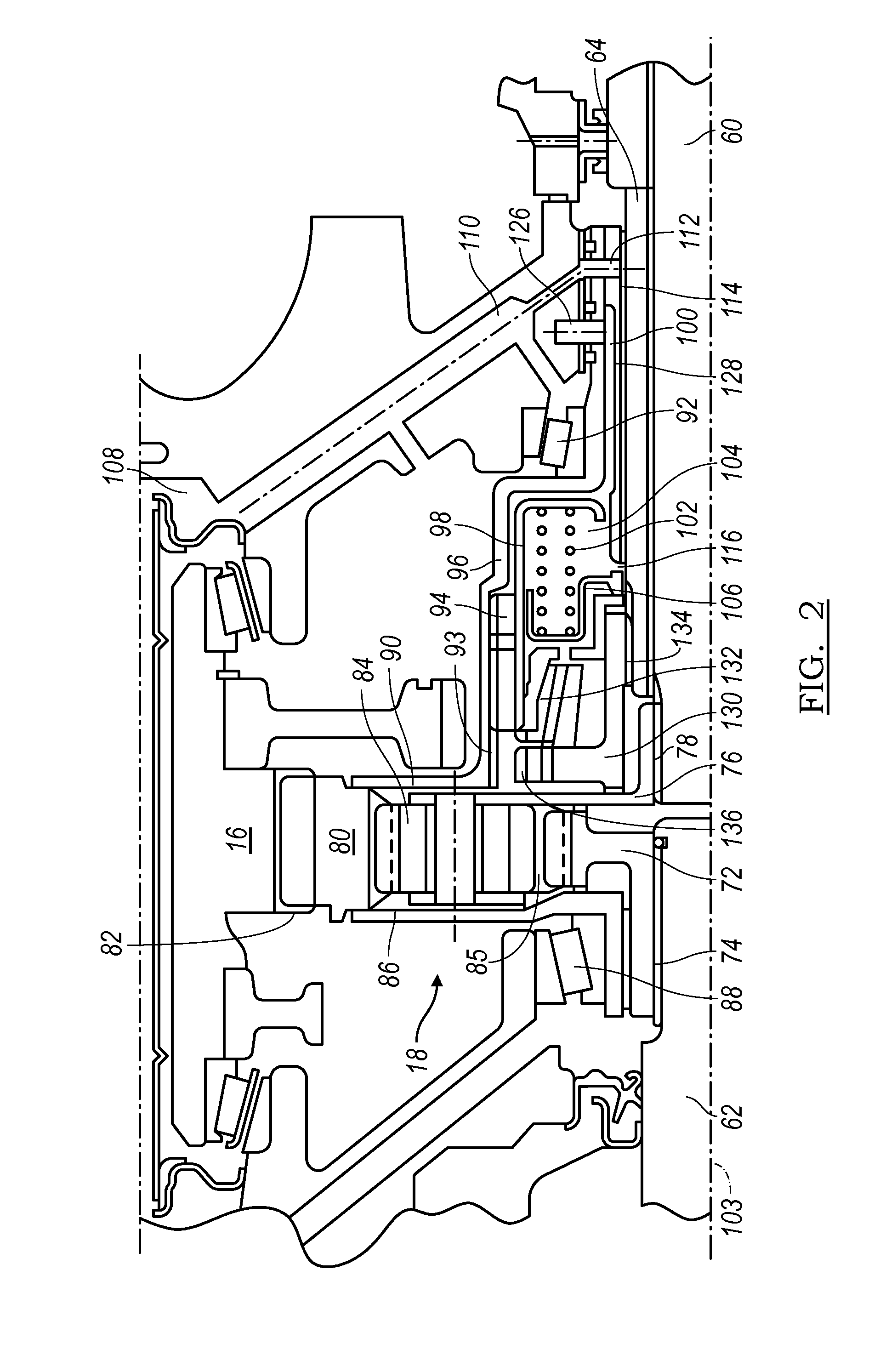
[0018]The PTU 24 comprises a coupler 34, such as a dog clutch or synchronizer, whose input is driveably conn...


PUM


Abstract

A method for controlling a vehicle driveline includes using current conditions to estimate wheel slip probability and vehicle dynamics handling support requirements, producing two-wheel drive operation, if said slip probability and handling support requirement is low and a condition for forced driveline connection is absent, and producing four-wheel drive operation, if said slip probability and / or handling support requirement is high and a condition for forced driveline disconnection is absent.

Description

BACKGROUND OF THE INVENTION[0001]1. Field of the Invention[0002]This invention relates generally to a motor vehicle driveline, which in operation transmits power continually to a first wheel set and selectively to a second wheel set.[0003]2. Description of the Prior Art[0004]All-wheel-drive (AWD) systems tend to reduce vehicle fuel economy due to increased driveline parasitic losses, even when AWD is not activated. Driveline disconnect systems improve fuel economy by disconnecting as many of the driveline rotating parts as possible, as close to the transmission output and the secondary drive wheels as possible, when all-wheel-drive is not activated.[0005]In virtually all front-wheel-drive (FWD) vehicles and many rear-wheel-drive (RWD) vehicles that produce all-wheel drive (AWD) or four-wheel drive (4WD), operation in two-wheel-drive (2WD) is not provided. In such vehicles, 2WD operation is produced in response to being manually selected by the vehicle operator. But requirement that ...

Claims


Application Information

Patent Timeline
19 Apr 2012
Publication
US20120095659A1
IPC
B60K28/16
CPC
B60Y2300/28; B60K23/08; B60K23/0808; B60W2550/148; B60W2550/12; B60W2550/147; B60K28/165; B60W2552/35
Inventors
RODRIGUES, ASHOK E.; PERAKES, ANDREAS E.