
Electric Tracklaying Gear and Use Thereof for a Self-Propelled Working Machine

a technology of tracklaying gear and working machine, which is applied in the direction of propulsion parts, propulsion mounting, transportation and packaging, etc., can solve the problems of increasing the thermal load affecting the performance and affecting the operation of the crawler drive. , to achieve the effect of reducing the thermal load and increasing the dust load

Active Publication Date: 2012-04-26
LIEBHERR COMPONENTS BIBERACH GMBH
View PDF2 Cites 8 Cited by
  • Summary
  • Abstract
  • Description
  • Claims
  • Application Information

AI Technical Summary

Benefits of technology

[0012]Therefore, it is the object underlying the present invention to create an improved electrically driven tracklaying gear for self-propelled working machines of the type mentioned above, which avoids the disadvantages of the prior art and develops the latter in an advantageous way. In particular a reduction of the thermal load of the crawler drive should be achieved, without paying for this with an increased dust load.

Problems solved by technology

However, this results in various problems.
The available installation space substantially is defined by the width of the track chain, so that longer motors with transmission units connected thereto often are too long or could only be mounted with a lateral protrusion.
On the other hand, cooling the drive units often is not possible to a sufficient extent, since a surface cooling or open-circuit cooling is not expedient for reasons of dust input.
In the case of forced ventilations, in addition, a strong generation and agitation of dust can be caused by a large stream of air emerging from the drive unit depending on the soil at the site of use, which is not acceptable in most uses.
However, this is not easily possible for the above-mentioned reasons and problems.
These known cooling solutions are, however, not expedient for use in tracklaying gears of construction machines, surface milling cutters, asphalt milling machines, excavators or the like for reasons of dust input which can be produced by a tracklaying gear operating in or on the soil.
On the other hand, a strong generation and agitation of dust can be caused by a large stream of air emerging from the motor depending on the soil at the site of use, which is not acceptable in most uses.
However, this does not solve the problem of the generation of dust by the emerging cooling air.
Nevertheless, a rest of dust input into the motor will remain, since the intake conduit cannot be designed arbitrarily high.
However, this involves the problem that the required large amounts of air require very large conduit cross-sections down into the tracklaying gear and back, which in terms of space can hardly be accommodated and can only be protected against mechanical damages with corresponding difficulties.

Method used


Image

  • Electric Tracklaying Gear and Use Thereof for a Self-Propelled Working Machine
  • Electric Tracklaying Gear and Use Thereof for a Self-Propelled Working Machine
  • Electric Tracklaying Gear and Use Thereof for a Self-Propelled Working Machine

Examples


Embodiment Construction

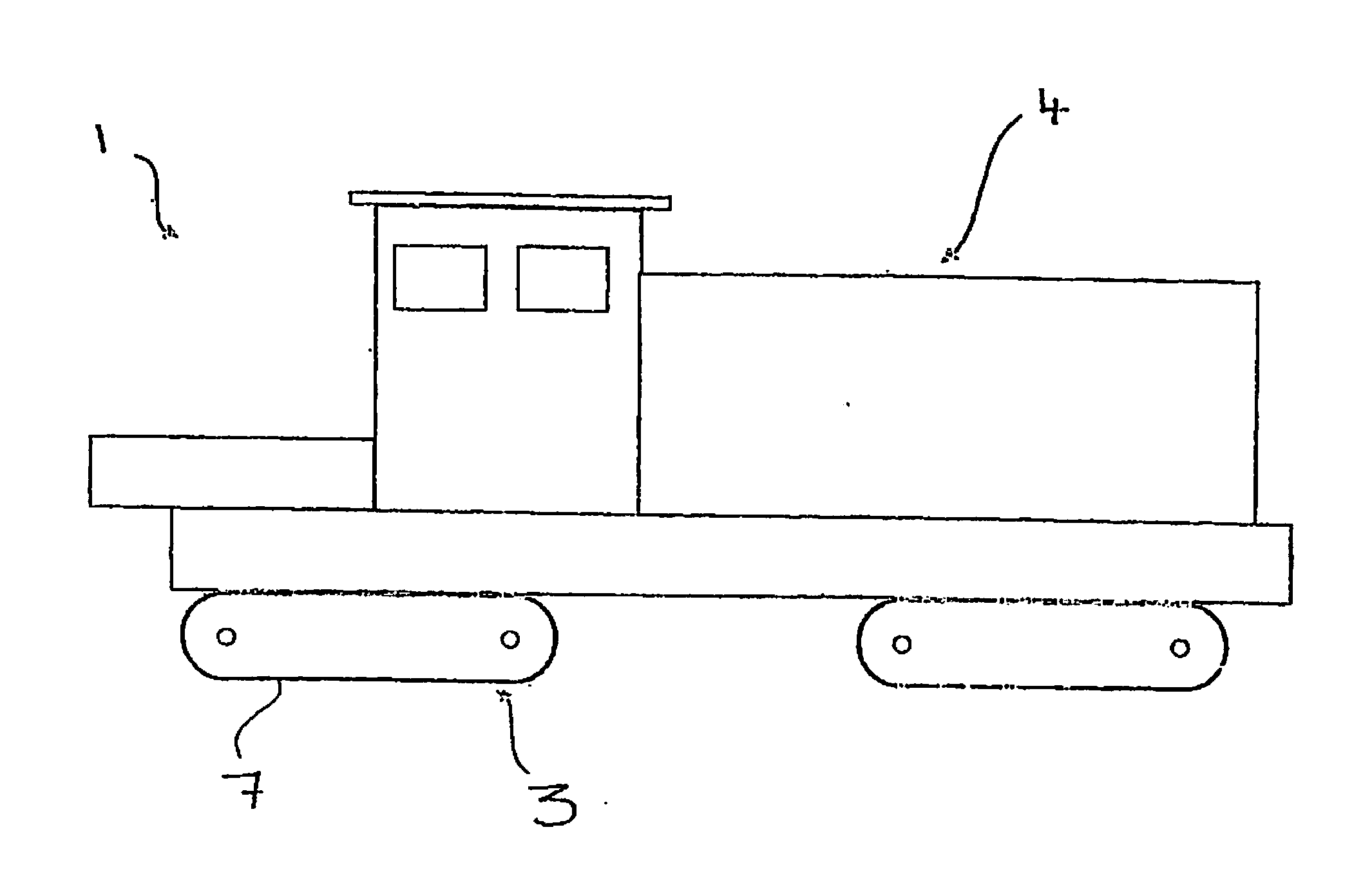
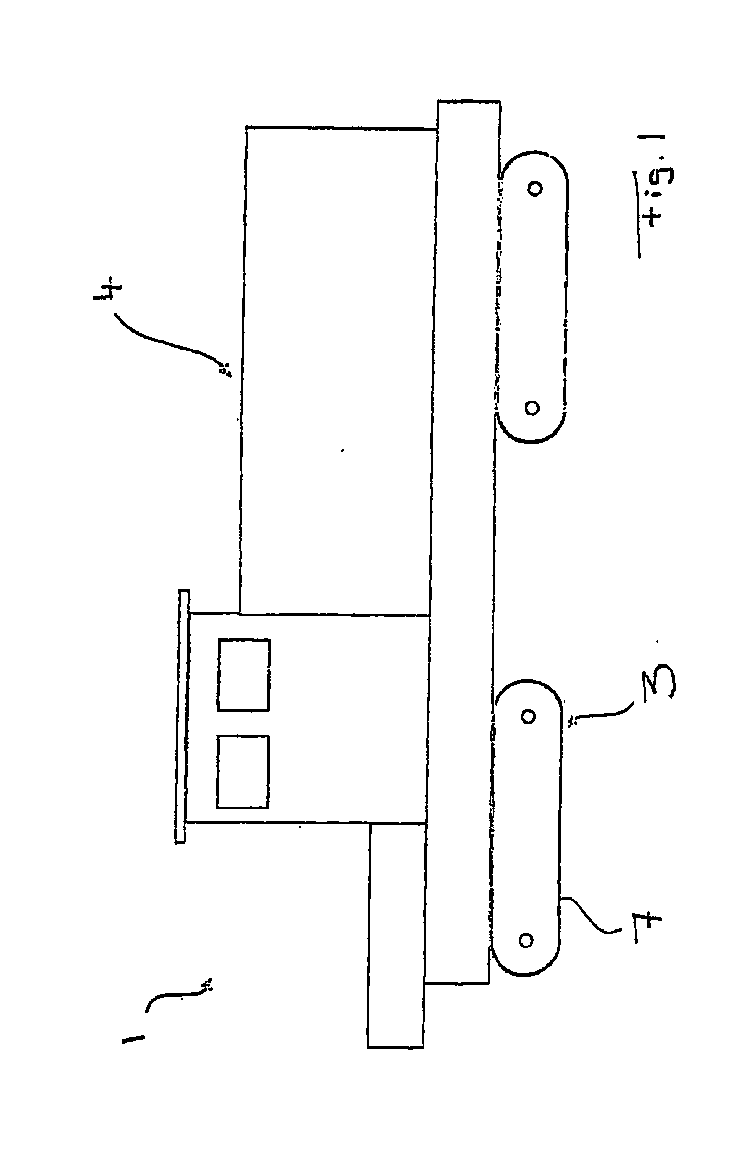
[0039]FIG. 1 shows a self-propelled working machine which can be moved by means of electrically driven tracklaying gears 3. The self-propelled working machine comprises the machine body 4 which is movably supported on the ground by said tracklaying gears 3.

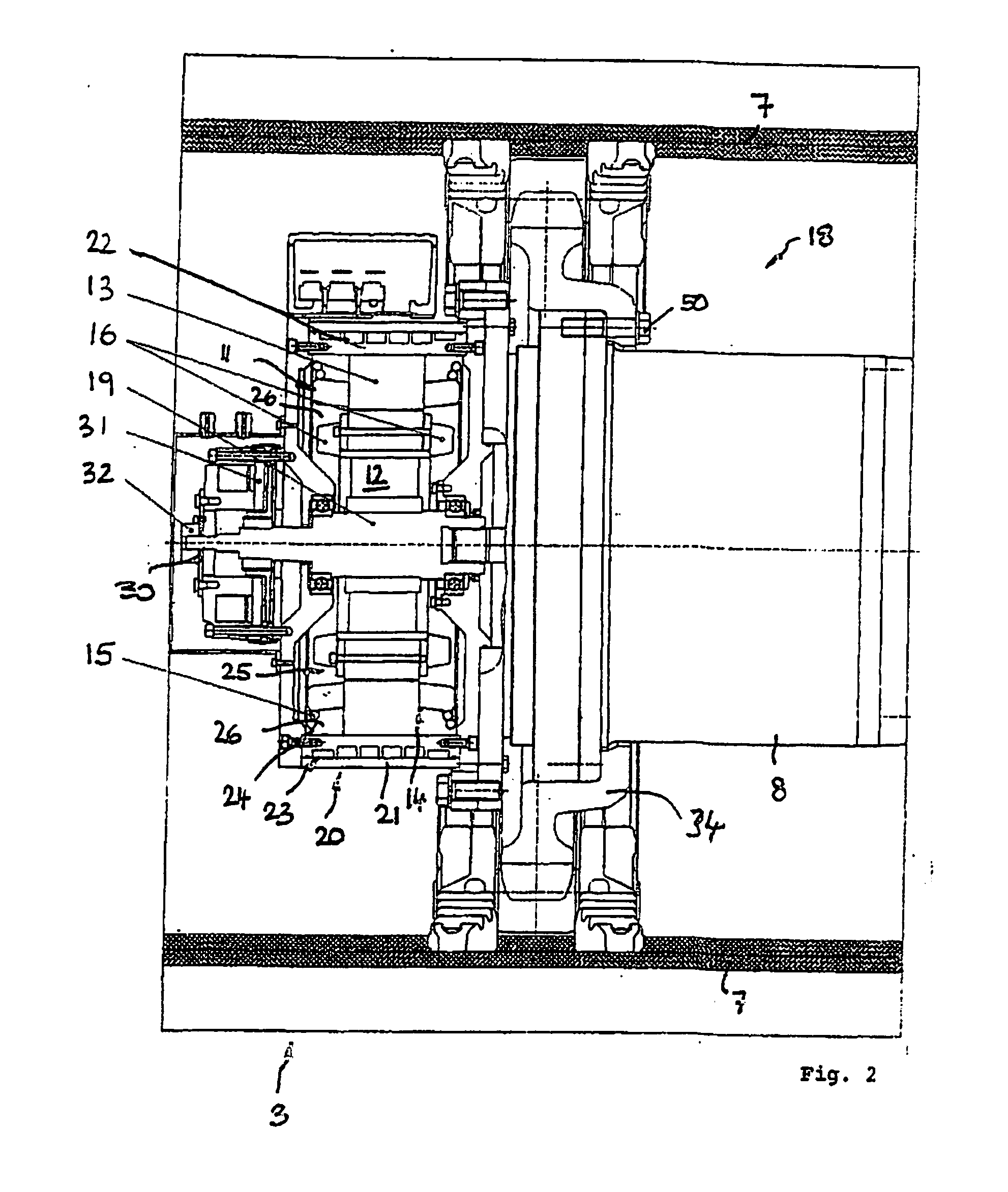
[0040]As shown in FIGS. 1 and 2, the tracklaying gear 3 in a manner known per se comprises a circulating track chain 7 which as a link chain for example can be made of a metallic material and can be deflected or supported via a plurality of deflection and support wheels and can be driven by at least one drive wheel 34 and at least one crawler drive connected therewith, as will be explained below.

[0041]As shown in FIG. 2, the crawler drive 18 comprises an electric motor 20 whose motor shaft 19 is connected with a transmission 8 in the form of a planetary transmission.

[0042]Said electric motor 20 advantageously is formed in the form of a synchronous motor with permanent-magnet rotor 12, which in the rotor has no rods, but permanent ...


PUM


Abstract

The present invention relates to an electric tracklaying gear and the use thereof for a self-propelled working machine, preferably for a construction or earth-moving machine or a surface mining machine such as Surface Miner, which includes an endlessly circulating track chain which can be driven by a crawler drive that is arranged inside the path of circulation of the track chain. It is proposed to associate a cooling device with a closed fluid cooling circuit to the electric motor of the crawler drive arranged in the interior of the path of circulation of the track chain. Due to the high thermal capacity of a suitable cooling fluid such as oil or water-glycol mixture small volumetric flow rates in the fluid cooling circuit and hence small conduit cross-sections are sufficient. On the other hand, due to the closed formation of the fluid cooling circuit any dust input into the crawler drive and also any generation of dust by exhaust air can be avoided.

Description

BACKGROUND OF THE INVENTION[0001]The present invention relates to an electric tracklaying gear and the use thereof for a self-propelled working machine, preferably for a construction or earth-moving machine or a surface mining machine such as Surface Miner, which includes an endlessly circulating track chain which can be driven by a crawler drive that is arranged within the path of circulation of the track chain.[0002]Such tracklaying gears are used for various machines of the type mentioned above such as hydraulic or cable excavators, mobile crawler cranes, bulldozers, asphalt milling machines or Surface Miners. The endlessly circulating track chain traditionally is a link chain made of a metallic material, but it can also mean a rubber chain or a similarly constructed moving belt which circulates endlessly.[0003]To protect the crawler drive against external damages and not increase the track width of the vehicle beyond the outer sides of the link chains, the crawler drive for driv...

Claims


Application Information

Patent Timeline
IPC IPC(8): B62D55/00B60K7/00B62D55/12
CPCB60K7/0007B60K17/043B60K2007/0038B60K2007/0092Y02T10/7258B62D55/088B62D55/125H02K9/19B62D55/06B60L2240/425Y02T10/64Y02T10/72H02K5/203
Inventor GRANER, KLAUSLIS, JOHANN
Owner LIEBHERR COMPONENTS BIBERACH GMBH
Learn More