Piping system

a technology of piping system and expansion joint, which is applied in the direction of adjustable joints, pipe joints, sleeves/socket joints, etc., can solve the problems of increasing the load on the equipment nozzle, insufficient load reduction measures, and difficulty in applying the simple untied bellows expansion joint when the pipe bore or internal pressure becomes larger, so as to reduce the load applied and increase the plant capacity

Inactive Publication Date: 2012-04-26
TOYO ENG CORP
View PDF7 Cites 11 Cited by
  • Summary
  • Abstract
  • Description
  • Claims
  • Application Information

AI Technical Summary

Benefits of technology

[0014]The present invention has been developed in view of the problems of the background art, and an object of the present invention is to provide a piping system that can reduce loads applied to an equipment nozzle with reliability although pipe bore is enlarged by recent trend to increase plant capacity.
[0019]Thus, according to the present invention, in the piping system, where pipes that are heavier than the equipment nozzle and that thermally expand (or thermally contract) due to the temperature of the internal fluids are connected, loads on the equipment can be reduced. As compared to the conventional design method in which a conventional hinge-type expansion joint, a gimbal type expansion joint and an universal expansion joint are used, a friction force or operation resistance that is applied to the equipment nozzle from the piping system can be more significantly reduced because the anchor set is set close to the nozzle. Moreover, the spring reaction forces of the bellows are canceled by using the displacement of the bellows caused by the thermal expansion of the piping members in the piping system, and hence loads on the equipment nozzle can be reduced more significantly than in the case of using the conventional pressure balanced type expansion joint.

Problems solved by technology

This makes it difficult to apply the simple untied bellows type expansion joint when a pipe bore or the internal pressure becomes larger.
However, this load reduction measure is becoming insufficient due to recent trend toward larger capacity plant.
A frictional force at a sliding portion such as the hinge or the gimbal increases, causing an increase in loads on the equipment nozzle.
Thus, an influence of the force in the spring hanger supports on the equipment nozzle can no longer be negligible.
As a result, this load becomes predominant, exceeding the allowable value of a load for the equipment nozzle.
This anchor prevent any piping load, friction and reaction force being transmitted to the equipment nozzle side from another side of the anchor by rigidly supporting the piping However, in the conventional art, this method has been difficult for the following reasons.
However, when the piping member close to the bellows is fixed, all axial thermal expansion at the equipment nozzle must be absorbed by compression displacement of the bellows.
As a result, the spring reaction force increases, and the loads on the equipment nozzle exceed the allowable value, making it impractical to set an anchor in the piping member close to the bellows within the scope of conventional art.

Method used


Image

  • Piping system
  • Piping system
  • Piping system

Examples


Embodiment Construction

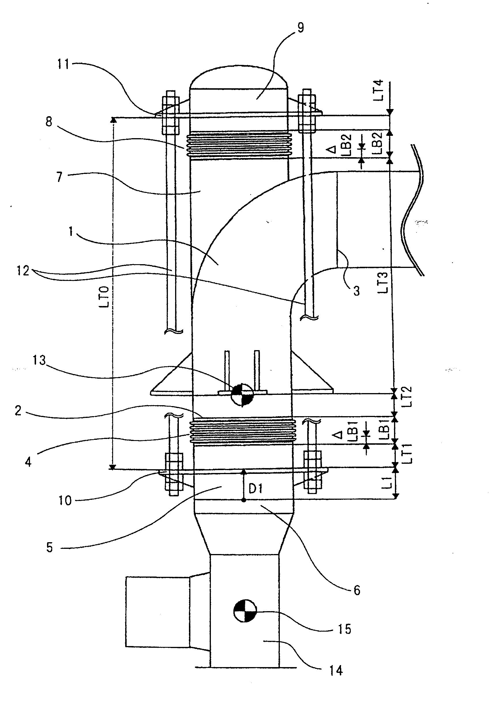
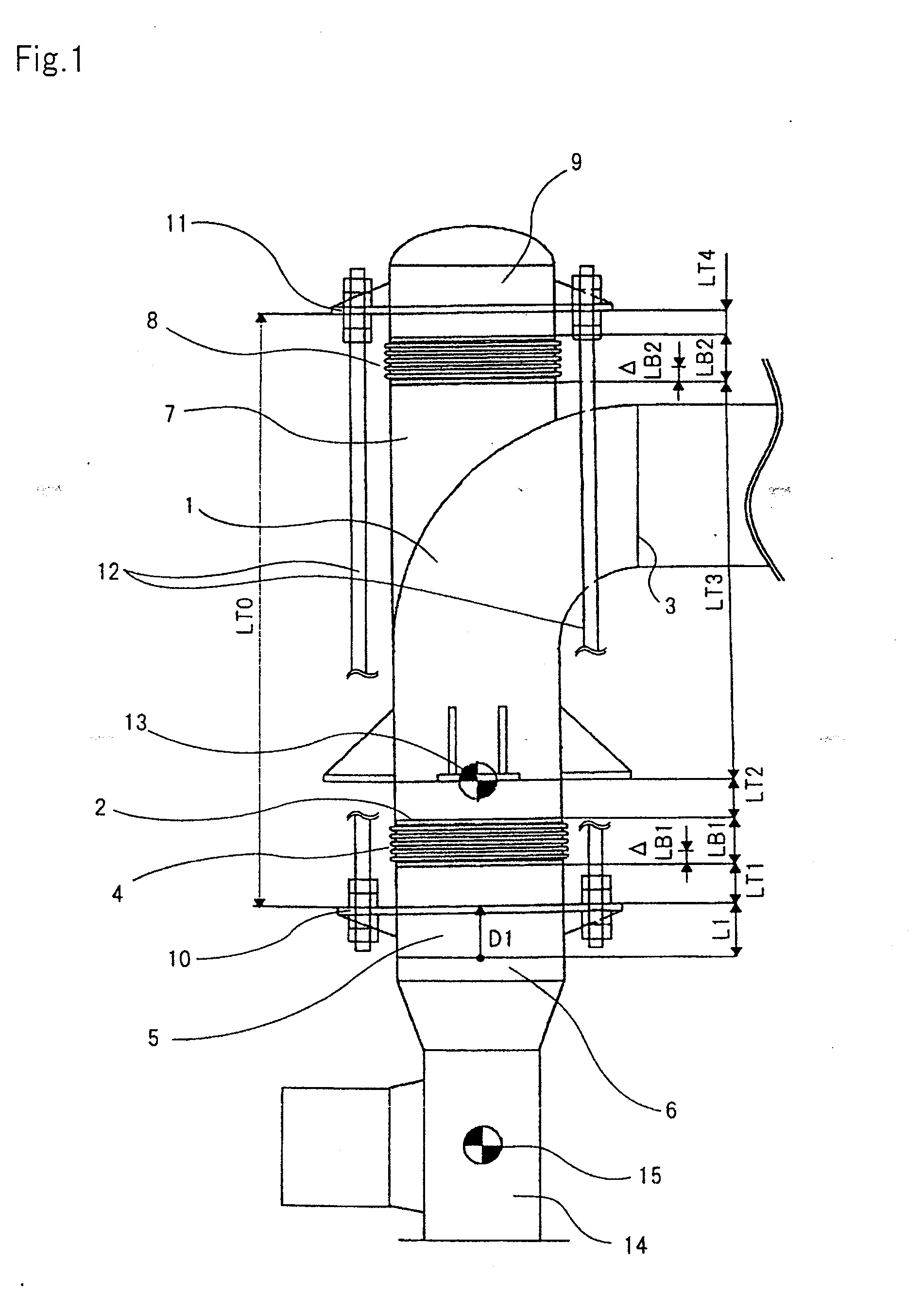
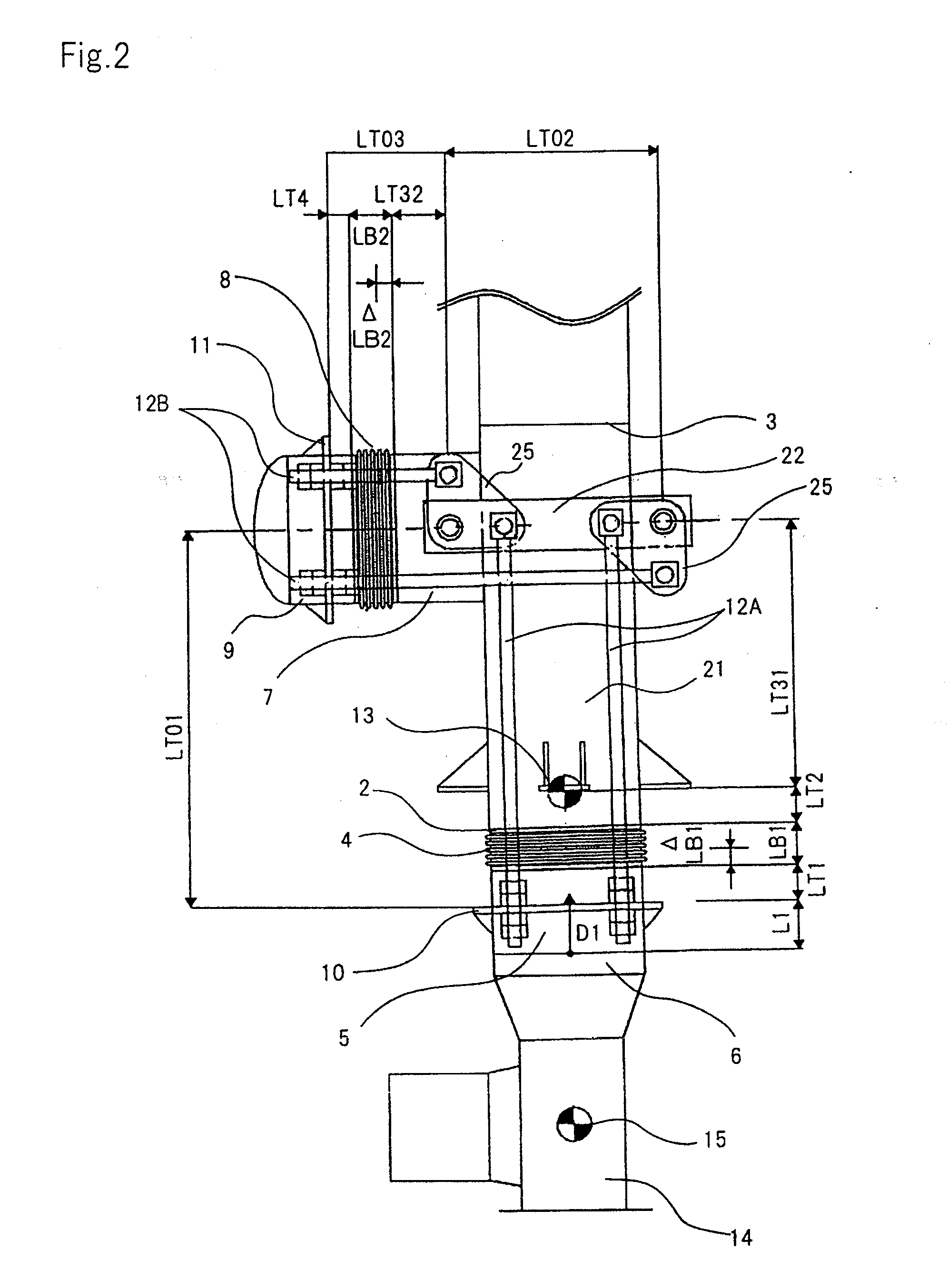
[0043]A piping system according to the present invention employs a bellows type expansion joint to which a pressure balance method is being applied. FIG. 1 is a side view showing in outline the pipingsystem according to an exemplary embodiment. As shown, a lower end of the piping system is connected to an equipment nozzle such as a rotary machine, and the piping system is an apparatus designed to reduce an external force (pipe self-weight, thermal expansion of a pipe, spring reaction force of a bellows, internal-pressure thrust, loads of other places, frictional force, or operation resistance) on the equipment nozzle.

[0044]FIG. 1 shows an example where a pipe extending in a horizontal direction is connected into the equipment nozzle. Referring to FIG. 1, elbow pipe (curved pipe) 1 has input terminal 2 and discharge terminal 3. Discharge terminal 3 of elbow pipe 1 is connected to the pipe that extends in the horizontal direction. Input terminal 2 of elbow pipe 1 is connected to strai...


PUM


Abstract

A piping system comprising: a main pipe; a first pipe member connecting an equipment nozzle and the main pipe via a first bellows; a second pipe member connected to a side part of the main pipe; a third pipe member connected to the other end of the second pipe member via a second bellows; first and second tie rod support members fixed to the first and third pipe members; tie rods that interconnect the tie rod support members; and an anchor that sets a portion of the main pipe as a fixed point. Lengths of the pipe members between the tie rod support members are determined so that the first bellows contracts by thermal expansion of the equipment nozzle, the first pipe member, and the pipe member of the main pipe below the anchor, and the second bellows contracts by an amount equally to that of the first bellows.

Description

[0001]This application is based upon and claims the benefit of priority from Japanese patent application No. 2010-239920, filed on Oct. 26, 2010, the disclosure of which is incorporated herein in its entirety by reference.BACKGROUND OF THE INVENTION[0002]1. Field of the Invention[0003]The present invention relates to a piping system connected to equipment in a petrochemical plant or a power plant. The equipment is a rotary machine such as an expander of a fluidized catalytic cracker (FCC) or to a high-temperature reactor, and the like in which the allowable value of a load applied from a pipe arrangement is small.[0004]2. Description of the Related Art[0005]Since the expander of the FCC has a precise rotational mechanism, any excessive force or moment must be prevented from being applied to an equipment of this type. Hence, in a metal piping system connected into an equipment nozzle installed in such an equipment, measures are taken to reduce loads on the nozzle.[0006]One of such me...

Claims


Application Information

Patent Timeline
Patent Type & Authority Applications(United States)
IPC IPC(8): F16L51/03
CPCF16L51/035F16L51/03F16L51/00F16L51/02F17D3/00
Inventor NODA, KENSUKE
Owner TOYO ENG CORP
Why Eureka
Try Eureka