LED light assembly and associated method

a technology of led light and assembly method, which is applied in the direction of lighting support devices, light source combinations, instruments, etc., can solve the problems of color distortion of objects, light energy, lamps, etc., and achieve the effect of improving chromatic consistency, improving uniform lighting of subjects, and improving chromatic consistency

Inactive Publication Date: 2012-04-26
WYBRON
View PDF2 Cites 14 Cited by
  • Summary
  • Abstract
  • Description
  • Claims
  • Application Information

AI Technical Summary

Benefits of technology

[0023]In another aspect of the present invention, the substrate, heat sink, and coolant flow generator are positioned in-line with one another. That is to say, the coolant flow generator is positioned to direct coolant fluid flow towards the heat sink that, in turn, is positioned to conduct away thermal energy from the substrate and are proximate to the LED light source. Thereby, by causing dissipation of the thermal energy away from the heat sink, the coolant fluid flow causes cooling of, or prevents the buildup of thermal energy proximate to, the LED light source, thereby to maintain the temperature level proximate to the LED light source at an acceptable level.
[0024]In another aspect of the present invention, the LED light source is comprised of a plurality of multiple, light-emitter elements. The elements are supported at a substrate in an array configuration. That is to say, individual ones of the multiple, light-emitter elements are supported at positions of the substrate to form an array of the elements. And, when supplied with operative power, the individual elements generate light energy that collectively defines a lamp output. Improved chromatic consistency is provided across a light beam forming the lamp output. And, resultant, uniform lighting of a subject is better provided.
[0025]In another aspect of the present invention, the multiple, light-emitter elements comprise quad LED elements with each quad LED element having four LED emitters. The LED emitters of the quad LED element include, for instance, a red LED emitter, a yellow LED emitter, a blue LED emitter, and a white LED emitter. In other implementations, the multiple, light-emitter elements are comprised of other numbers and colors of LED light emitters. The array into which the LED light-emitter elements are arranged comprises, e.g., a rectangular array or a circular array. In one implementation, the light-emitter elements are grouped into groups of four-element groups with each element of the group rotationally offset from another element in the group by approximately 90 degrees. Thereby, the different ones of the light-emitter elements of the group have different-colored LED emitters in different quadrants defined by each of the quad-emitter elements. Analogously, in an implementation in which the light-emitter elements are configured in a circular, or other radio-like array, the individual ones of the light-emitter elements are rotationally offset from other elements. For instance, adjacent-positioned elements of the array are rotationally offset from elements adjacent thereto. Improved chromatic consistency is provided across a light beam forming the lamp output. And, resultant, uniform lighting of a subject is better provided.

Problems solved by technology

Some gas-discharge lamps, however, have a low color rendering index, resulting in color distortion of objects that are illuminated by the gas-discharge lamp, light energy.
These lamps also, however, suffer from a similar disadvantage as that exhibited by incandescent lamps.
Furthermore, the extent of the dimming that is possible in this manner is also limited.
That is to say, the range of the dimming is limited.
But, the dimming cannot continue down to a zero output.
Additionally, if the operating temperature about a LED lamp exceeds a maximum threshold, LED lamp is susceptible to permanent damage, permanently reducing the light-intensity capability of the lamp.
This dissimilar output power response across a range of operating temperatures causes a relative change in the magnitudes of the individual colors being created by the lighting fixture which results in a color shift when the light is viewed on the intended target.
Therefore, while lighting devices utilizing LED lamps provide advantageous over lighting devices utilizing conventional lamps, challenges remain in their use, particularly in high-intensity lighting applications.

Method used


Image

  • LED light assembly and associated method
  • LED light assembly and associated method
  • LED light assembly and associated method

Examples


Embodiment Construction

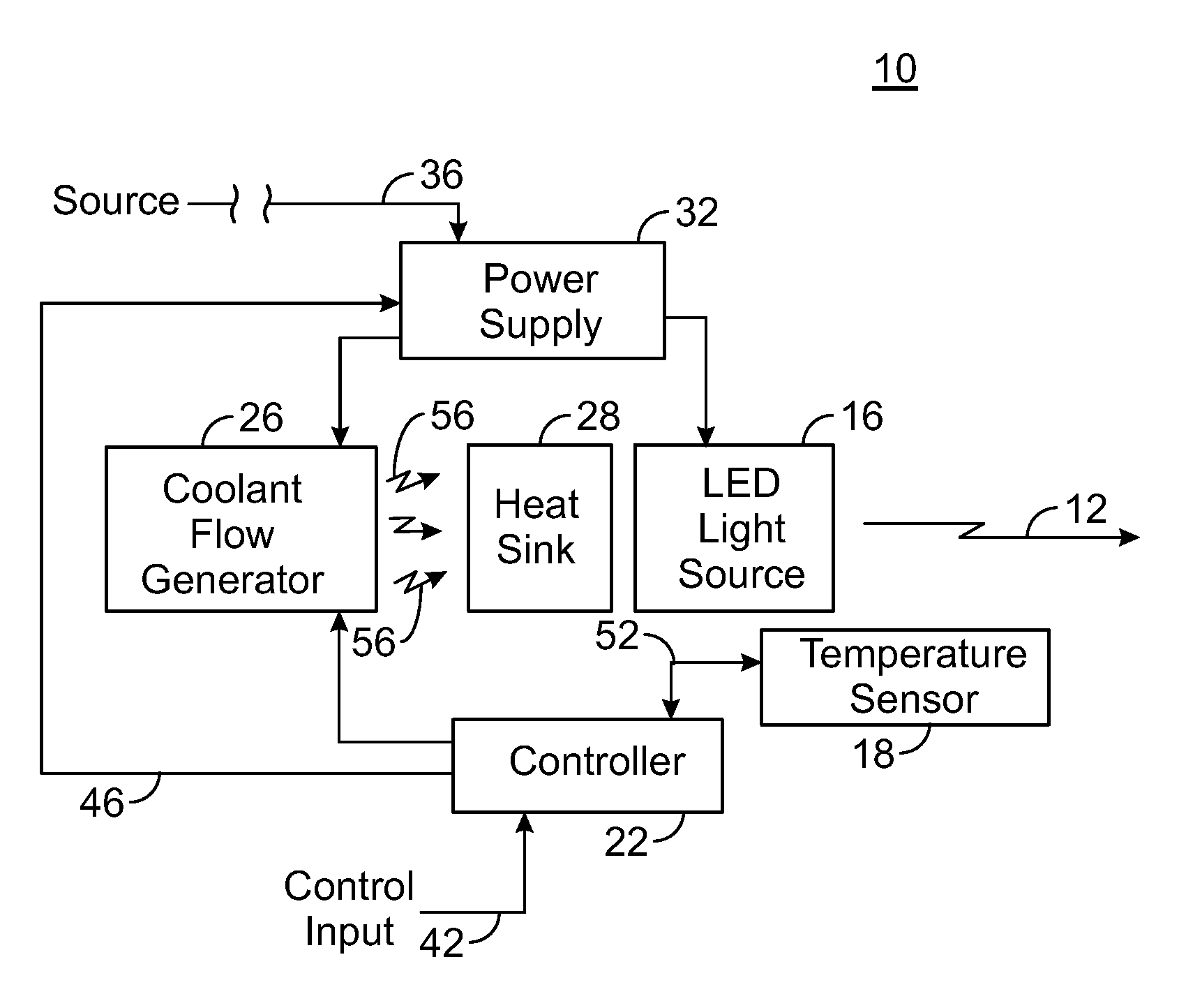
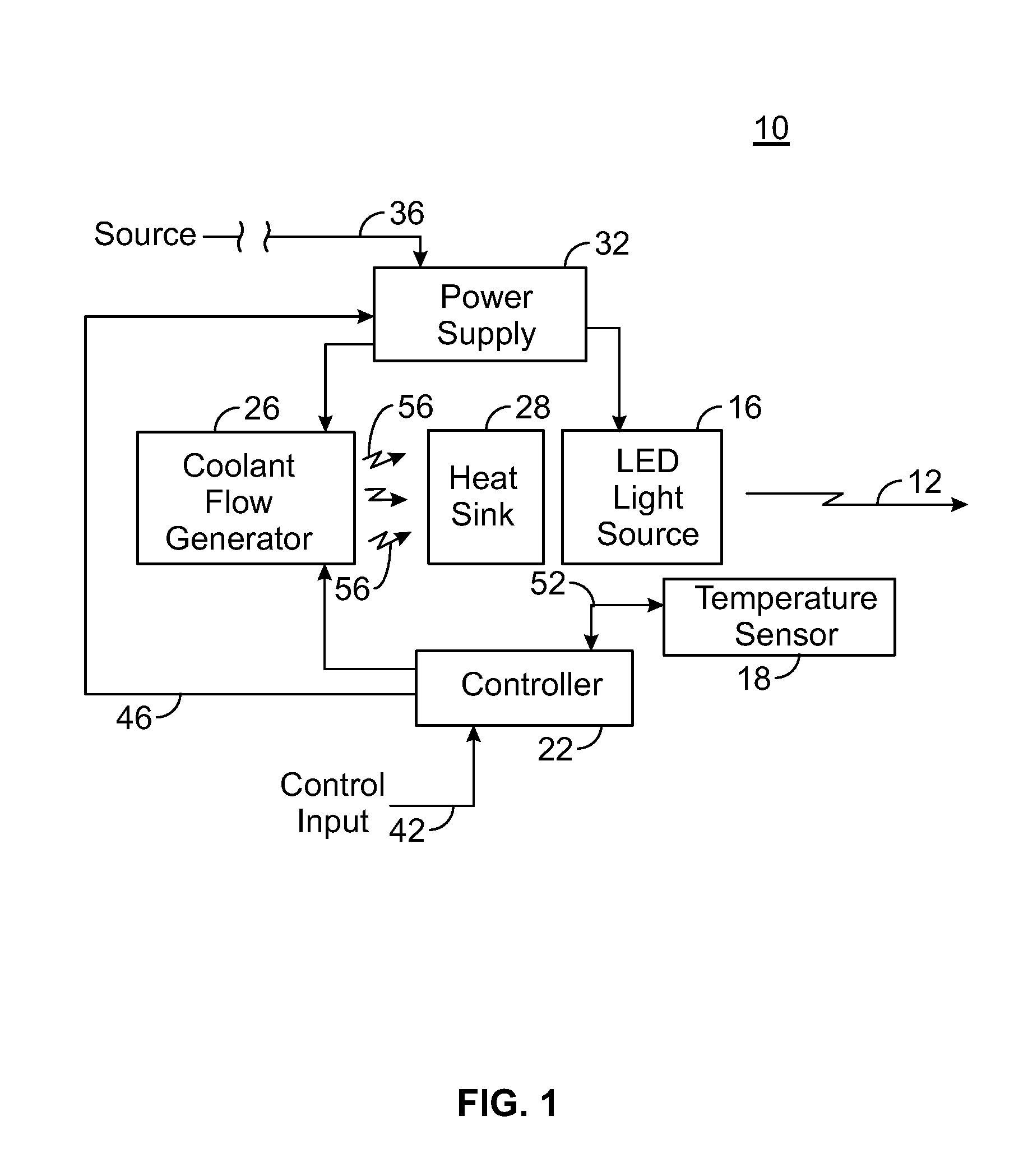
[0034]Turning first, therefore, to FIG. 1, a light assembly, shown generally at 10, operates to generate light energy defining a lamp output, here represented by the arrow 12. The light assembly, in the exemplary implementation, comprises a high-power light assembly capable of generating light energy of high intensity, such as light energy generated pursuant to a stage-lighting application. While the following description of exemplary operation of the light assembly 10 shall be described with respect its implementation in which the light assembly is constructed as a stage light, in other implementations, the light assembly is configured to generate light energy pursuant to effectuation of other lighting applications. Additionally, while the elements of the light assembly are functionally represented, the elements are implemented in any desired manner that provides the functionalities of the respective elements.

[0035]The light assembly 10 is here shown to include an LED (Light Emitti...


PUM


Abstract

A light assembly, and an associated method, provides color-mixed light generated by light emitter diode elements. A temperature sensor is position to sense temperature levels proximate to the LED light-emitter elements. And, a coolant flow generator is configured in a feedback arrangement to generate coolant fluid to dissipate thermal energy generated during operation of the LED elements to maintain the temperature levels at a constant temperature or within an allowable range.

Description

[0001]The present invention relates generally to a light assembly, such as a light assembly used to illuminate an object that utilizes LED (Light Emitting Diode) lights. More particularly, the present invention relates to an LED light assembly, and an associated method, that utilizes a plurality of multiple-LED elements, arranged in an array and that maintains a temperature level substantially constant in proximity to the LED elements.[0002]The LED assembly provides light energy of consistent characteristics, relative to an applied power level, that also is of improved color mixing characteristics.BACKGROUND OF THE INVENTION[0003]Lighting devices are used to provide artificial illumination pursuant to many various light functions. Lighting devices are constructed to generate light energy forming a lamp output of various light intensities and various colors. And, while many of such light devices are needed merely to generate a lamp output of static, non-changing attributes, some ligh...

Claims


Application Information

Patent Timeline
Patent Type & Authority Applications(United States)
IPC IPC(8): H01J13/32F21S4/00H05B37/02H01J61/52
CPCF21Y2101/02F21Y2105/003F21Y2113/005F21V29/763H05B33/0872F21V29/677H05B33/0803F21Y2105/10F21Y2105/12F21Y2113/13F21Y2115/10H05B45/00H05B45/20
Inventor SONDERICKER, III, JOHN H.
Owner WYBRON
Why Eureka
Try Eureka