
Spim microscope with a sted light sheet

a technology of sted light and microscope, applied in the field of spim microscope, can solve the problems of low optical resolution along the optical axis in the detection direction, system is quite rigid, and high thickness of illuminated volume, so as to increase the flexibility of microscope, increase the flexibility of choosing illumination, and increase the flexibility of choosing

Active Publication Date: 2012-04-26
LEICA MICROSYSTEMS CMS GMBH
View PDF16 Cites 62 Cited by
  • Summary
  • Abstract
  • Description
  • Claims
  • Application Information

AI Technical Summary

Benefits of technology

[0008]It is an object of the invention to increase the flexibility of the microscope described at the outset, in particular to increase the flexibility in choosing the illumination volume and to increase the flexibility in choosing the type of microscopy that is applied.
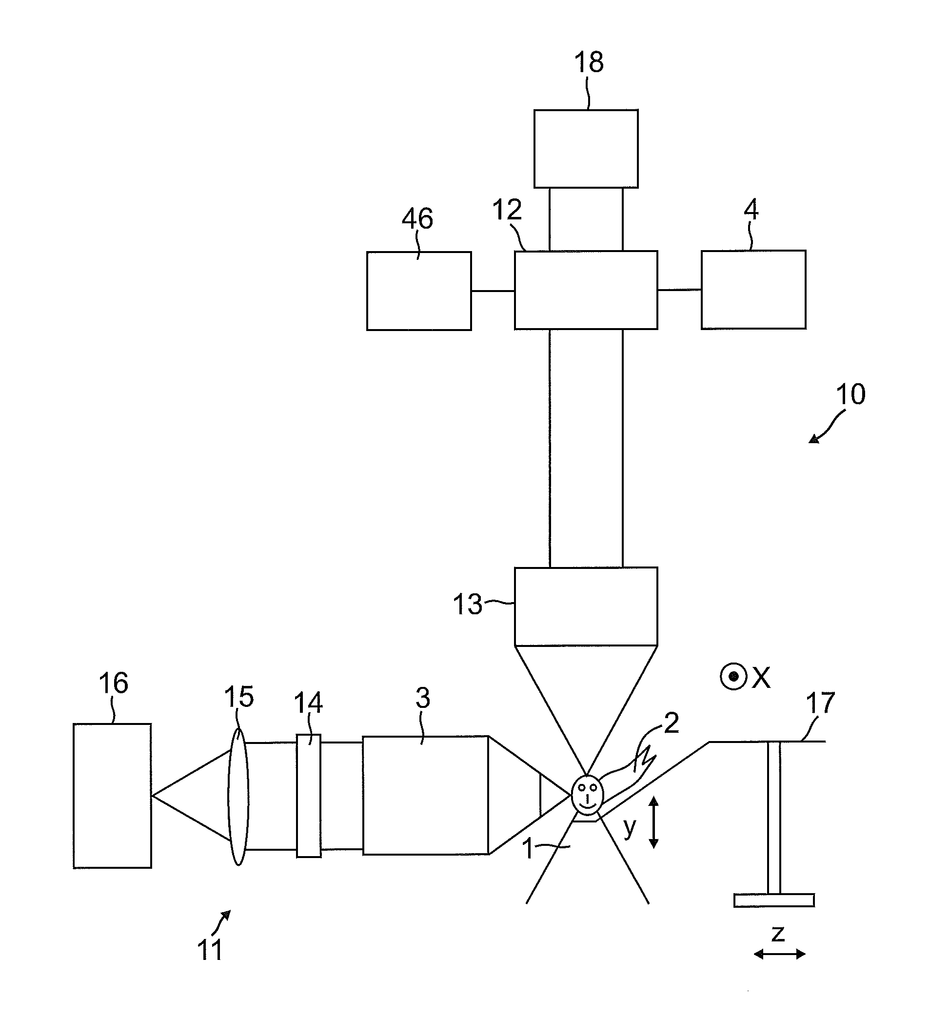
[0010]According to a preferred embodiment of the invention a deactivation light beam modulator is provided that is adapted to modulate the deactivation light beam such that its cross-section comprises in z-direction at least two intensity maxima with a zero point in between that is provided in the center of the excitation light beam. In the alternative, the deactivation beam can also be modulated so that the side lobes (side maxima) of the deactivation light beam are also deactivated. In this case, it is advantageous if the peaks of the side lobes of the excitation light beam coincide with the peaks of the deactivation light beam. It is possible to modulate the excitation light beam such that stronger side lobes are generated. This allows making the main maximum longer and thinner. Stronger side lobes (side maxima) result in case of non-deactivation in decreasing the resolution in the z-direction. If, however, the side maxima are deactivated, the resolution is increased.

Problems solved by technology

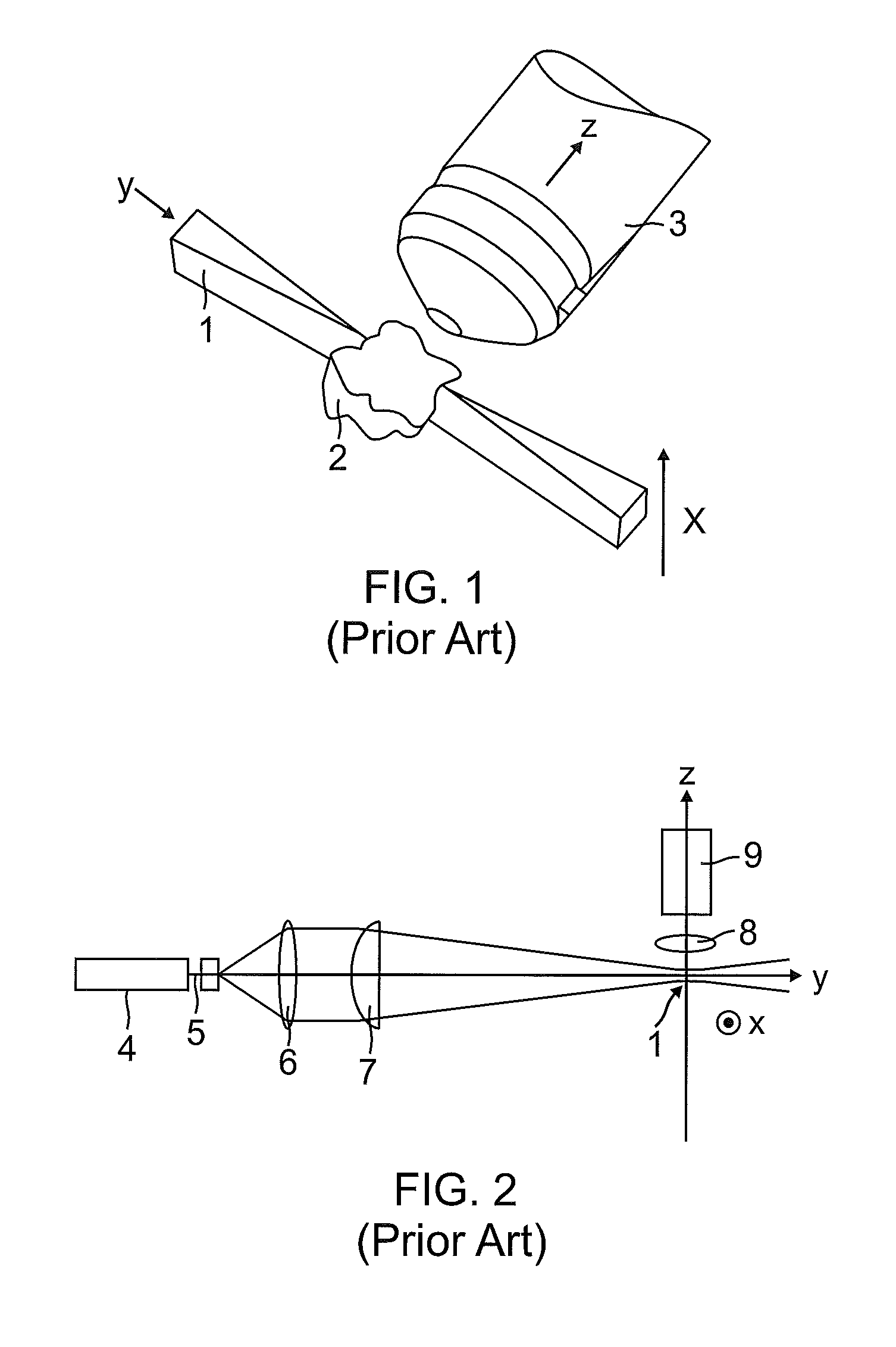
Generating a light sheet according to the prior art SPIM technology using a cylindrical lens has the disadvantage that the system is quite unflexible, for instance provides a fixed focus and therefore a predetermined illuminated volume.
This means that a long focus that results from selecting a low numerical aperture of the illumination optics has the consequence that also the thickness of the illuminated volume is high.
This means that the optical resolution along the optical axis in the detection direction is likewise low.
Depending on the practical application the consequence is a conflict of goals: If a high depth of penetration of the illumination light should be achieved, an elongate focus is required that does, however, result in a thicker light sheet and therefore in a lower resolution.

Method used


Image

  • Spim microscope with a sted light sheet
  • Spim microscope with a sted light sheet
  • Spim microscope with a sted light sheet

Examples


Embodiment Construction

[0010]According to a preferred embodiment of the invention a deactivation light beam modulator is provided that is adapted to modulate the deactivation light beam such that its cross-section comprises in z-direction at least two intensity maxima with a zero point in between that is provided in the center of the excitation light beam. In the alternative, the deactivation beam can also be modulated so that the side lobes (side maxima) of the deactivation light beam are also deactivated. In this case, it is advantageous if the peaks of the side lobes of the excitation light beam coincide with the peaks of the deactivation light beam. It is possible to modulate the excitation light beam such that stronger side lobes are generated. This allows making the main maximum longer and thinner. Stronger side lobes (side maxima) result in case of non-deactivation in decreasing the resolution in the z-direction. If, however, the side maxima are deactivated, the resolution is increased.

[0011]Furthe...


PUM


Abstract

A STED-SPIM-microscope (Selective Plane Imaging Microscopy) having a y-direction illumination light source and a z-direction detection light camera. An x-scanner generates a sequential light sheet by scanning the illumination light beam in the x-direction. By optionally turning on a STED deactivation light beam the light sheet can optionally be made thinner and therefore the optical resolution can be increased.

Description

CROSS-REFERENCE TO RELATED APPLICATIONS[0001]This application claims the priority of the German patent application DE 102010060121.7 having a filing date of Oct. 22, 2010 and claims priority of the European patent application EP 11169989.8 having a filing date of Jun. 15, 2011. The entire content of this prior German patent application DE 102010060121.7 and the prior European patent application EP 11169989.8 is herewith incorporated by reference.BACKGROUND OF THE INVENTION[0002]The invention relates to a SPIM-microscope comprising a light source sending an illumination light beam from a y-direction onto an object to be imaged and a camera detecting in a z-direction as a first detection direction light emanating from the object as fluorescent light and / or as reflected light, wherein the z-direction extends substantially perpendicular to the y-direction.[0003]In particular, biological samples should be analyzed both quickly and without damaging the sample. For many applications, it is...

Claims


Application Information

Patent Timeline
IPC IPC(8): H04N7/18
CPCG02B21/002G02B21/16G02B21/06G02B21/361G02B21/0084G01N21/6458G02B21/0032G02B21/0076G02B21/367G02B21/10
Inventor KNEBEL, WERNEROESTREICHER, WOLFGANG
Owner LEICA MICROSYSTEMS CMS GMBH
Learn More