Wavelength conversion laser light source and image display device

a laser light source and wavelength conversion technology, applied in the direction of laser details, instruments, light demodulation, etc., can solve the problems that conventional technologies do not address the stabilization of the resonator, and achieve the effect of high wavelength conversion efficiency and stable outpu

Inactive Publication Date: 2012-04-26
PANASONIC CORP
View PDF10 Cites 11 Cited by
  • Summary
  • Abstract
  • Description
  • Claims
  • Application Information

AI Technical Summary

Benefits of technology

[0013]It is an object of the present invention to provide a wavelength conversion laser light source which has high wavelength conversion efficiency and produces a stable output.

Problems solved by technology

However, these conventional technologies do not address issues about stabilization of the resonator.

Method used


Image

  • Wavelength conversion laser light source and image display device
  • Wavelength conversion laser light source and image display device
  • Wavelength conversion laser light source and image display device

Examples


first embodiment

[0043]A wavelength conversion laser light source according to the first embodiment is mainly characterized by a “non-converting region” which is formed on an emission end surface side of the wavelength convertor. The term “non-converting region” means a region which has little contribution to the wavelength conversion from the fundamental wave light to the second harmonic light.

(Structure of Wavelength Conversion Laser Light Source)

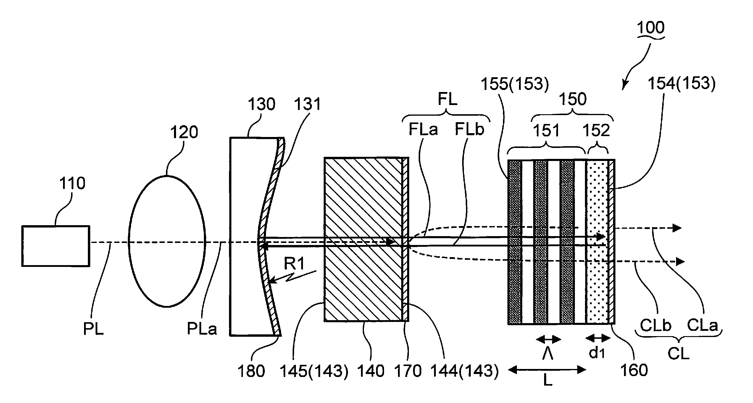
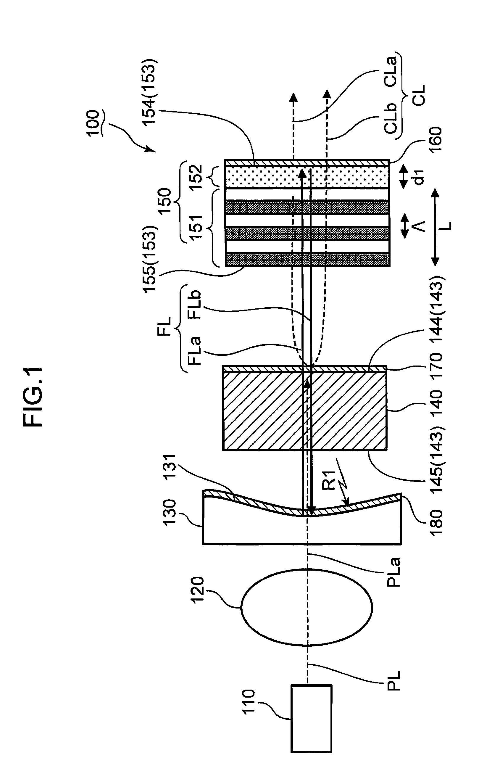
[0044]FIG. 1 is a schematic view of the wavelength conversion laser light source according to the first embodiment. The wavelength conversion laser light source is described with reference to FIG. 1.

[0045]The wavelength conversion laser light source 100 according to the present embodiment comprises: an excitation laser light source 110 which generates excitation laser light PL; a condensing lens 120 which condenses the excitation laser light PL; a concave lens 130 which includes a concave surface 131 formed with a curvature R1; a solid laser medium 140 wh...

second embodiment

[0081]FIG. 4 is a schematic view of a wavelength conversion laser light source according to the second embodiment. The wavelength conversion laser light source according to the second embodiment is described with reference to FIG. 4.

[0082]The wavelength conversion laser light source 100A according to the present embodiment comprises a wavelength convertor 150A in addition to the excitation laser light source 110, the condensing lens 120, the concave lens 130, the solid laser medium 140 and the dielectric multi-layer films 160, 170, 180, like the wavelength conversion laser light source 100 described in the context of the first embodiment. The wavelength convertor 150A includes a non-converting region 152A in addition to the wavelength converting region 151 described in the context of the first embodiment. A polarization reversal structure which does not contribute to the conversion from the fundamental wave light FL to the second harmonic light CL is formed in the non-converting reg...

third embodiment

[0085]FIG. 6 is a schematic view of a wavelength conversion laser light source according to the third embodiment. The wavelength conversion laser light source according to the third embodiment is described with reference to FIG. 6.

[0086]The wavelength conversion laser light source 100B according to the present embodiment comprises a wavelength convertor 150B in addition to the excitation laser light source 110, the condensing lens 120, the concave lens 130, the solid laser medium 140 and the dielectric multi-layer films 160, 170, 180 like the wavelength conversion laser light source 100 described in the context of the first embodiment. The wavelength convertor 150B includes a non-converting region 152B in addition to the wavelength converting region 151 described in the context of the first embodiment. Like the wavelength converting region 151, a periodic polarization reversal structure is formed in the non-converting region 152B. The polarization reversal direction of the polarizat...


PUM

PropertyMeasurementUnit
lengthaaaaaaaaaa
angleaaaaaaaaaa
wavelengthaaaaaaaaaa

Abstract

A wavelength conversion laser light source having: a laser medium which generates a fundamental wave light; a laser resonator for causing laser oscillation of the fundamental wave light; a wavelength convertor which is provided with a wavelength converting region to convert the fundamental wave light under the laser oscillation by means of the laser resonator into converted light of a different wavelength; and an excitation laser light source for exciting the laser medium, wherein the laser resonator has at least one reflecting surface which reflects the fundamental wave, and a first reflecting element which is provided on an end surface of the wavelength convertor to reflect the fundamental wave light ; the wavelength converting region is situated between the at least one reflecting surface and the first reflecting element; the wavelength convertor has a periodic first polarization reversal structure formed in the wavelength converting region, and a non-converting region formed between the first reflecting element and the wavelength converting region; and the non-converting region does not convert the fundamental wave light into the converted light.

Description

TECHNICAL FIELD[0001]The present invention is related to a wavelength conversion laser light source and an image display device.BACKGROUND OF THE INVENTION[0002]A laser light source is widely used as a built-in device incorporated into industrial devices or domestic devices. A semiconductor laser diode or a solid-state laser light source is exemplified as the laser light source. A wavelength conversion laser light source is exemplified as another laser light source to obtain laser beam of a wavelength which is hardly obtained by means of direct oscillation by the semiconductor laser diode or the solid-state laser light source.[0003]A wavelength conversion laser light source typically comprises a wavelength convertor. The wavelength conversion laser light source converts the fundamental wave laser beam (hereinafter, called “fundamental wave light”), which is incident on a wavelength convertor, into a frequency of laser beam by means of a Second Harmonic Generation element (SHG elemen...

Claims


Application Information

Patent Timeline
Patent Type & Authority Applications(United States)
IPC IPC(8): G02F1/37H01S3/10
CPCG03B21/14G03B21/20H01S3/08036H01S3/09415H01S3/109G02F2001/3548H01S3/1673G02F1/3532G02F1/3544G02F2001/3503H01S3/1611G03B21/2033G02F1/3503G02F1/3548
Inventor HORIKAWA, NOBUYUKIKUSUKAME, KOICHISUGITA, TOMOYAFURUYA, HIROYUKI
Owner PANASONIC CORP
Why Eureka
Try Eureka