
Dispensing toothbrush

a toothbrush and toothpaste technology, applied in the field of coating implements, can solve the problems of not being widely accepted in the market, not being practical to carry a conventional toothbrush and toothpaste tube in a pocket or purse, and compartmented toothbrushes have not seen widespread commercial acceptance, etc., to achieve the effect of convenient use, low cost and compact siz

Inactive Publication Date: 2012-04-26
DESBRUNES HERMAN
View PDF4 Cites 3 Cited by
  • Summary
  • Abstract
  • Description
  • Claims
  • Application Information

AI Technical Summary

Benefits of technology

[0003]In light of the problems associated with the known toothbrushes, it is a principal object of my invention to provide a dispensing toothbrush that is: compact in size, resistant to leaks, lightweight in construction, inexpensive to manufacture, and dependable in use.
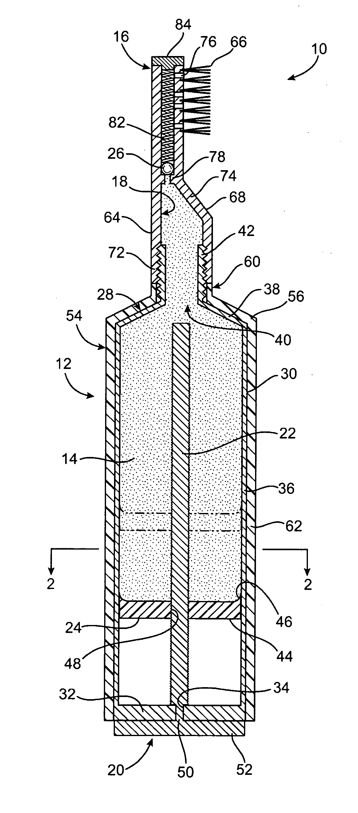
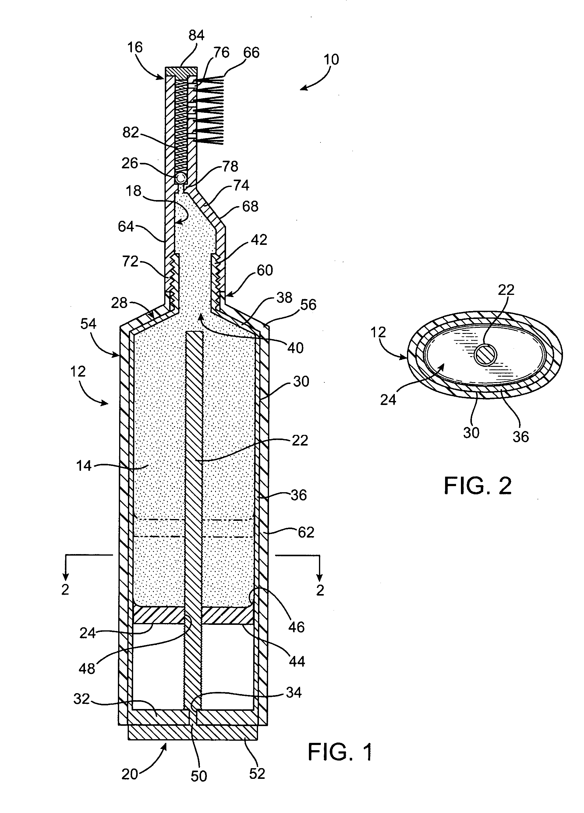
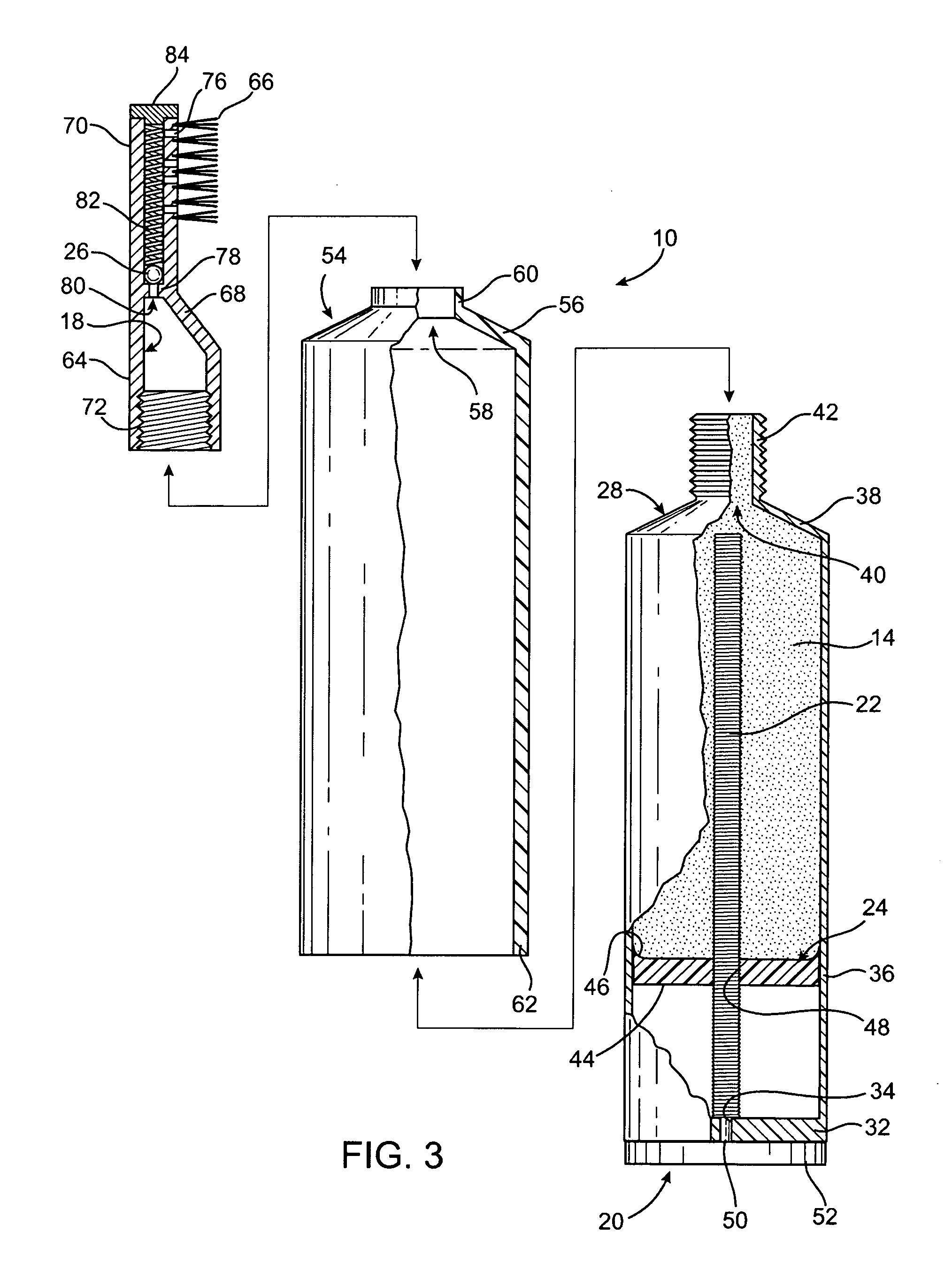
[0005]Briefly, my dispensing toothbrush achieves the intended objects by featuring a hollow handle. Toothpaste is positioned within the handle. A piston is positioned within the handle below the toothpaste. A brush is affixed to the top of the handle. The brush has an internal channel in fluid communication with the handle that provides a way for toothpaste to exit the toothbrush. A ball valve is positioned within the channel for preventing toothpaste from inadvertently leaking from the toothbrush. A thumbscrew is rotatably secured to the handle. The thumbscrew includes a threaded rod positioned within the handle. The threaded rod is threadably engaged with the piston. A knob is affixed to the bottom of the threaded rod and is positioned outside of the handle. Rotating the knob causes the piston to be driven upwardly so as to push toothpaste from the handle, past the ball valve, and from the brush.

Problems solved by technology

Unfortunately, it is not practical to carry a conventional toothbrush and tube of toothpaste in a pocket or purse since they are both bulky and prone to contaminate whatever they contact with toothpaste.
Compartmented toothbrushes have, however, not seen widespread commercial acceptance due to their generally complicated constructions, design flaws, and high costs.

Method used


Image

  • Dispensing toothbrush
  • Dispensing toothbrush
  • Dispensing toothbrush

Examples


Embodiment Construction

[0012]Referring now to the FIGS., a dispensing toothbrush is shown at 10. The toothbrush 10 includes a tubular handle 12 filled with toothpaste 14. A brush 16 is affixed to the top of the handle 12. The brush 16 has an internal channel 18 that provides a way for the toothpaste 14 to exit the toothbrush 10. A thumbscrew 20 is rotatably secured to the bottom of the handle 12. The thumbscrew 20 has a threaded rod 22 that extends the length of the handle 12. Positioned on the threaded rod 22 is a piston 24 that can be driven upwardly by rotating the thumbscrew 20 to push toothpaste 14 from the handle 12 and through the brush 16. A ball valve 26 positioned in the channel 18 prevents toothpaste 14 from inadvertently leaking from the handle 12.

[0013]The handle 12 includes a toothpaste reservoir 28 formed of lightweight plastic. The reservoir 28 has a container 30 within which is positioned a movable piston 24. The thumbscrew is rotatably secured to both the container 30 and the piston 24. ...


PUM


Abstract

A dispensing toothbrush includes a hollow handle. Toothpaste is positioned within the handle. A piston is positioned within the handle below the toothpaste. A brush is affixed to the top of the handle. The brush has an internal channel in fluid communication with the handle that provides a way for toothpaste to exit the toothbrush. A ball valve is positioned within the channel for preventing toothpaste from inadvertently leaking from the toothbrush. A thumbscrew is rotatably secured to the handle. The thumbscrew includes a threaded rod positioned within the handle. The threaded rod is threadably engaged with the piston. A knob is affixed to the bottom of the threaded rod and is positioned outside of the handle. Rotating the knob causes the piston to be driven upwardly so as to push toothpaste from the handle, past the ball valve, and from the brush.

Description

FIELD OF THE INVENTION[0001]The present invention relates generally to coating implements with material supply and, more particularly, to brushes, brooms, or mops with flow regulators.BACKGROUND OF THE INVENTION[0002]Dentists recommend that everyone should brush their teeth after meals to prevent tooth decay. Unfortunately, it is not practical to carry a conventional toothbrush and tube of toothpaste in a pocket or purse since they are both bulky and prone to contaminate whatever they contact with toothpaste. Some people have proposed toothbrushes with internal, toothpaste-carrying compartments as a way to get around these problems. Compartmented toothbrushes have, however, not seen widespread commercial acceptance due to their generally complicated constructions, design flaws, and high costs. Therefore, a need exists for a compact and uncomplicated toothbrush that does not leak and that permits users to easily brush their teeth wherever they may be. Many users of my toothbrush woul...

Claims


Application Information

Patent Timeline
Patent Type & Authority Applications(United States)
IPC IPC(8): A47L13/22
CPCA46B11/0027A46B2200/1066A46B11/0079
Inventor DESBRUNES, HERMAN
Owner DESBRUNES HERMAN
Learn More