Captive fastener

a technology of captive fasteners and mounting bases, which is applied in the direction of fastening means, securing devices, screws, etc., can solve the problems of affecting the operation of further re-installation, color index coasting to face or to drop, loosening or weakening corrosion-resistant and moisture-resistant properties, etc., to avoid fading of color index coating thereof or damage to color index coating. , to achieve the effect of accurate bonding of mounting base members and avoiding

Inactive Publication Date: 2012-04-26
HANWIT PRECISION IND LTD
View PDF10 Cites 37 Cited by
  • Summary
  • Abstract
  • Description
  • Claims
  • Application Information

AI Technical Summary

Benefits of technology

[0007]The present invention has been accomplished under the circumstances in view. It is therefore an object of the present invention to provide a captive fastener design, which facilitates accurate bonding of the mounting base member thereof to a panel frame and avoids fading of the color index coating thereof or damage to the color index coating during a high temperature bonding.
[0008]To achieve these and other objects of the present invention, a captive fastener comprises a mounting base member, a cap, a spring member, a locking shank and a driving member. The mounting base member is bonded to a mounting through hole of a first panel frame, comprising a chamber, a positioning portion downwardly extended from the bottom side thereof for insertion into the mounting through hole of the first panel frame, an axle hole axially extending through the positioning portion in communication between the chamber and the atmosphere, a shoulder defined between the chamber and the axle hole and a locating portion disposed at the top side thereof. The cap is mounted in the locating portion of the mounting base member, having a center hole. The locking shank is axially movably mounted in the mounting base member and adapted for engaging into a mounting through hole of the second panel frame to lock the second panel frame to the first panel frame, comprising a shank body inserted through the center hole of the cap and suspending in the chamber of the mounting base member, an engagement portion axially extended from one end of the shank body and inserted through the axle hole of the mounting base member for engaging into the mounting through hole of the second panel frame to lock the second panel frame to the first panel frame, and a stop flange extending around the periphery thereof between the shank body and the engagement portion and stoppable at the shoulder inside the mounting base member. The spring member is sleeved onto the shank body of the locking shank in the chamber and stopped between the stop flange of the locking shank and the cap for returning the locking shank after the locking shank having moved. The driving member is operable to move the locking shank axially relative to the mounting base member between a locking position and an unlocking position, comprising a connecting portion disposed at one side thereof for connection to the shank body of the locking shank. Further, the driving member is coated with a layer of color index coating for identification and for protection against corrosion and moisture. The driving member is to be fastened to the locking shank after bonding the mounting base member to the first panel frame. Thus, the color index coating of the driving member is kept intact when bonding the mounting base member to the first panel frame under a high temperature environment.

Problems solved by technology

When unlocking the panel frames, the component parts of the fastening screw assemblies may fall from the panel frames and missed accidentally, affecting further re-installation operation.
However, when bonding the mounting barrel of a captive screw or captive fastener to a panel frame by reflow soldering, the high temperature in the reflow oven may cause the color index coasting to face or to drop.
1. When a captive screw or captive fastener is delivered with a panel frame into reflow oven for reflow soldering, the high temperature in the reflow oven will cause the color index coasting of the captive screw or captive fastener to face or to drop, loosening or weakening the corrosion-resistant and moisture-resistant properties.
2. When all the component parts of a captive screw or captive fastener are delivered with a panel frame into reflow oven for reflow soldering, the captive screw or captive fastener may be forced to loose its balance and to fall out of position, resulting in a bonding failure or inaccurate bonding.

Method used


Image

  • Captive fastener
  • Captive fastener
  • Captive fastener

Examples


Embodiment Construction

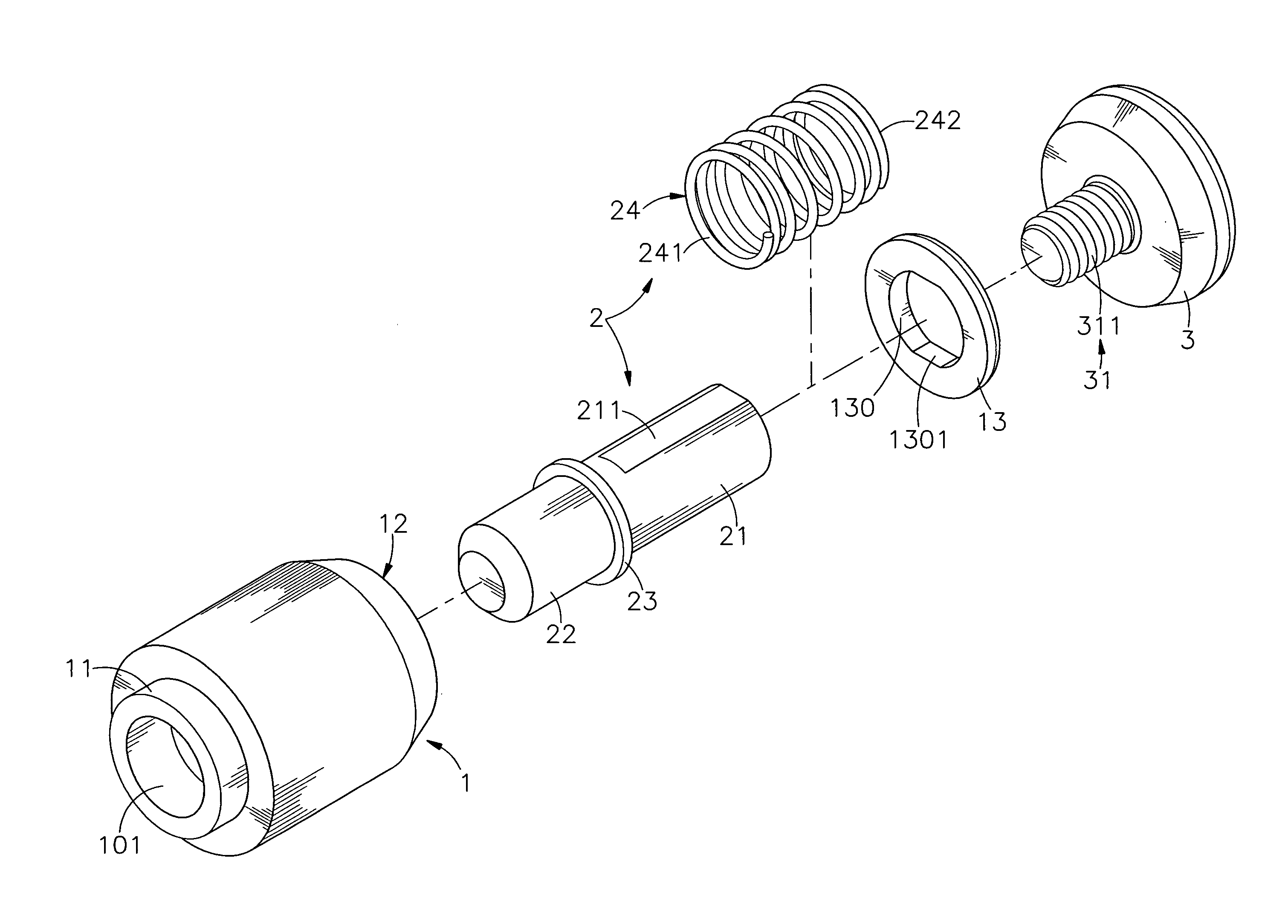
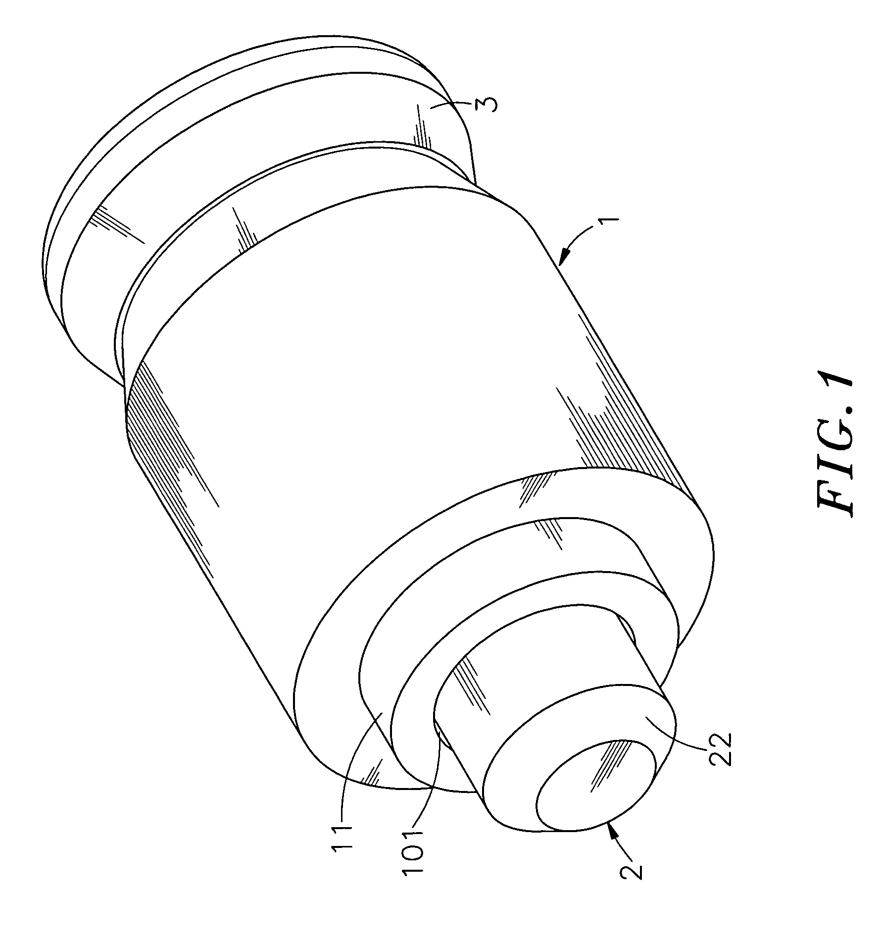
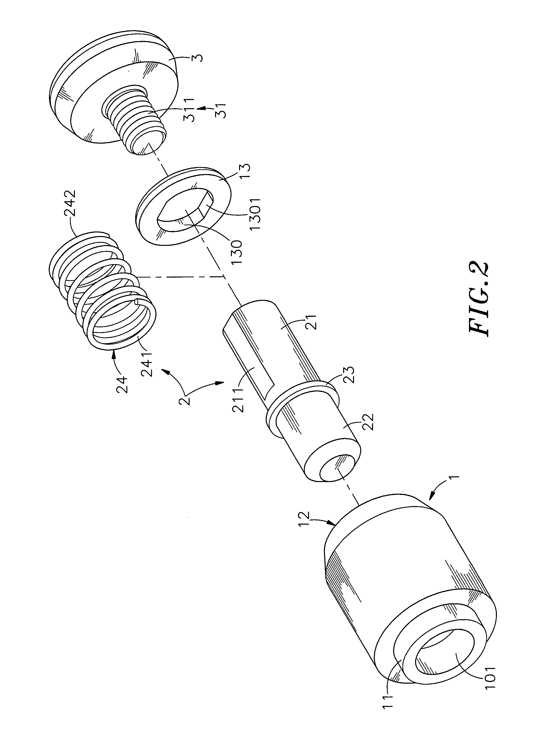
[0017]Referring to FIGS. 1˜3, a captive fastener in accordance with the present invention is shown comprising a mounting base member 1, a locking shank 2 and a driving member 3.

[0018]The mounting base member 1 comprises a chamber 10, a positioning portion 11 downwardly extended from its one side, namely, the bottom side, an axle hole 101 axially extending through the positioning portion 11 in communication between the chamber 10 and the atmosphere, a shoulder 102 defined between the chamber 10 and the axle hole 101 and a locating portion 12 disposed at its other side, namely, the top side. Further, a cap 13 is mounted in the locating portion 12, having a center hole 130 slightly smaller than the inner diameter of the chamber 10.

[0019]The locking shank 2 comprises a shank body 21, an engagement portion 22 axially extended from one end, namely, the bottom end of the shank body 21, a stop flange 23 extending around the periphery thereof between the shank body 21 and the engagement port...


PUM


Abstract

A captive fastener includes a mounting base member bonded to a first panel frame, a locking shank loaded with a spring member and axially movably mounted in the mounting base member hole for engaging into a mounting through hole of a second panel frame to detachably lock the second panel frame to the first panel frame, and a driving member, which is coated with a color index coating for identification and connected to the locking shank after bonding the mounting base member to the first panel frame and operable to move the locking shank between a locking position where the first panel frame and the second panel frame are locked and an unlocking position where the first panel frame is detachable from the second panel frame.

Description

BACKGROUND OF THE INVENTION[0001]1. Field of the Invention[0002]The present invention relates to fastener means for joining two metal panel frames and more particularly, to a captive fastener, which has the locking shank operating driving member thereof to be fastened to the locking shank after bonding of the mounting base member thereof to a first panel frame so that the color index coating of the driving member is kept intact during reflow soldering of the mounting base to the first panel frame.[0003]2. Description of the Related Art[0004]When fastening panel frames together, a fastening screw assembly formed of a knob, a barrel and a screw is usually used. During installation, the screw and the barrel are secured to the first panel frame, and then the knob is rotated to drive the screw into the second panel frame, and then a hand tool is used to fasten tight the screw, affixing the first and second panel frames together. This design of fastening screw assembly can be used in a ma...

Claims


Application Information

Patent Timeline
Patent Type & Authority Applications(United States)
IPC IPC(8): F16B39/24
CPCF16B1/0071F16B37/061F16B5/0266F16B5/0208F16B2200/95
Inventor CHIU, MING-CHUNG
Owner HANWIT PRECISION IND LTD
Why Eureka
Try Eureka