Ultrasonic diagnostic device

a diagnostic device and ultrasonic technology, applied in diagnostics, medical science, applications, etc., can solve the problems of blood flow power decline, blood flow velocity and blood flow power loss, etc., to display a blood flow moving picture smoothly, and accurately sense any variation in blood flow

Inactive Publication Date: 2012-04-26
KONICA MINOLTA INC
View PDF5 Cites 7 Cited by
  • Summary
  • Abstract
  • Description
  • Claims
  • Application Information

AI Technical Summary

Benefits of technology

[0033]According to the present invention, an aliasing decision is made based on the respective blood flow velocity data of the current frame and an earlier frame that precedes the current frame, and changes a persistence coefficient dynamically according to a result of the aliasing decision and based on the blood flow velocity data of the current frame. Consequently, the present invention provides an ultrasonic diagnostic apparatus that can accurately sense any variation in blood flow and that can display a blood flow moving picture smoothly without causing any blackout even at a low blood flow velocity.
[0034]In addition, according to the present invention, two persistence-processed blood flow velocities are obtained using two persistence coefficients that have been determined based on the respective blood flow velocity data of the current and earlier frames, and one of the two blood flow velocities that has the greater absolute value is chosen and used to display a blood, flow image. As a result, even the blood flowing through a peripheral blood vessel, where the blood flow power will often lose its stability, can be displayed constantly without flickering. And a blood flow moving picture can be displayed consistently without letting an overly smoothed blood, flowing through the peripheral blood vessel, disappear from the screen.

Problems solved by technology

For that reason, the blood flow velocity and the blood flow power (representing the rate of blood flowing) to be obtained by color flow mapping signal processing tend to lose their stability.
Particularly if the region of interest has a low blood flow velocity or is a peripheral vessel, the blood flow power decreases so much that information about the blood flow velocity or the blood flow power tends be lost very easily during noise reduction processing to cut down only system noise or acoustic noise.
In that case, the blood flow portion will suddenly disappear from the tomographic image, thus decreasing the smoothness of the image or making the viewer sense unnaturalness.

Method used


Image

  • Ultrasonic diagnostic device
  • Ultrasonic diagnostic device
  • Ultrasonic diagnostic device

Examples


embodiment 1

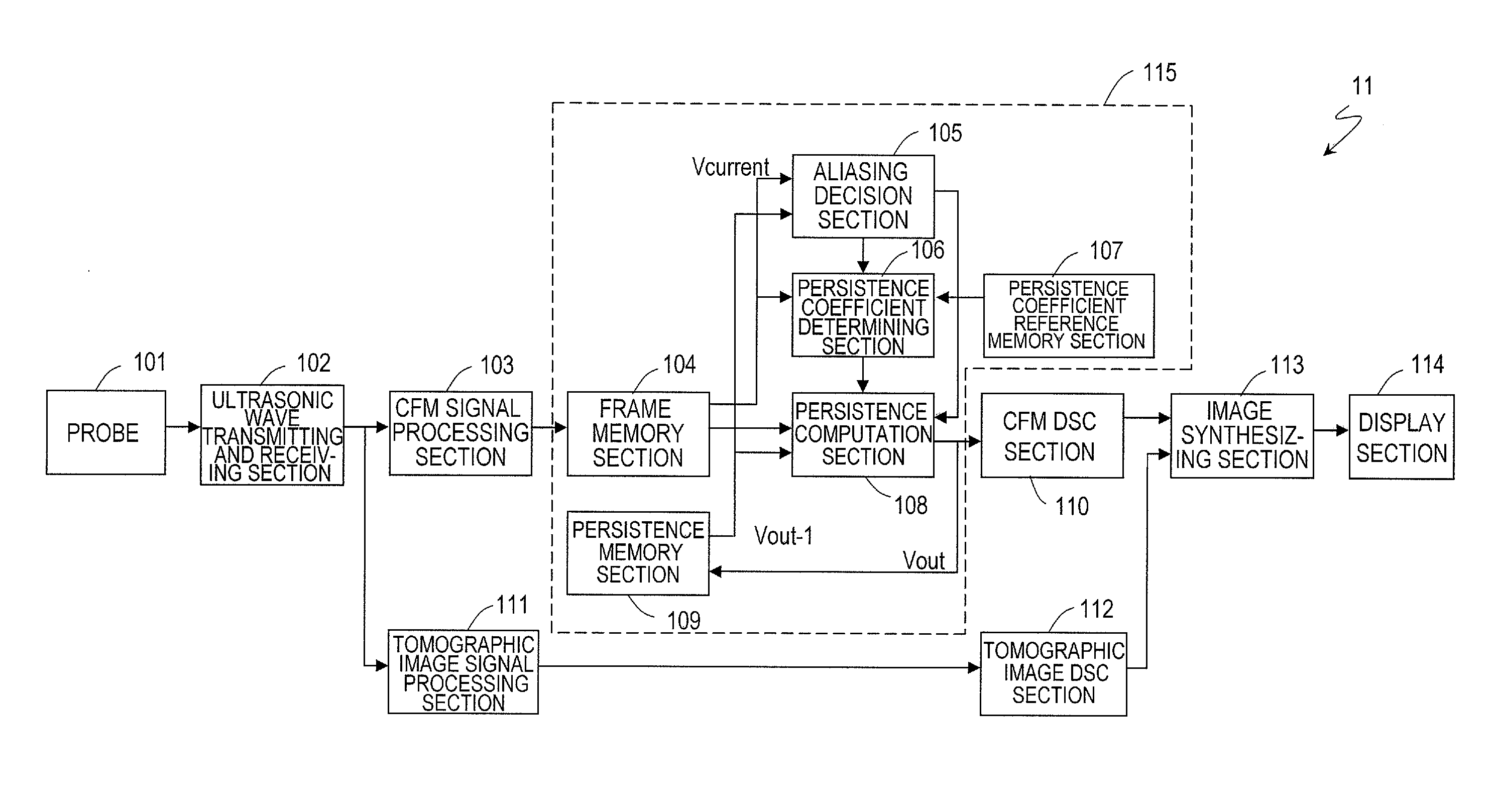
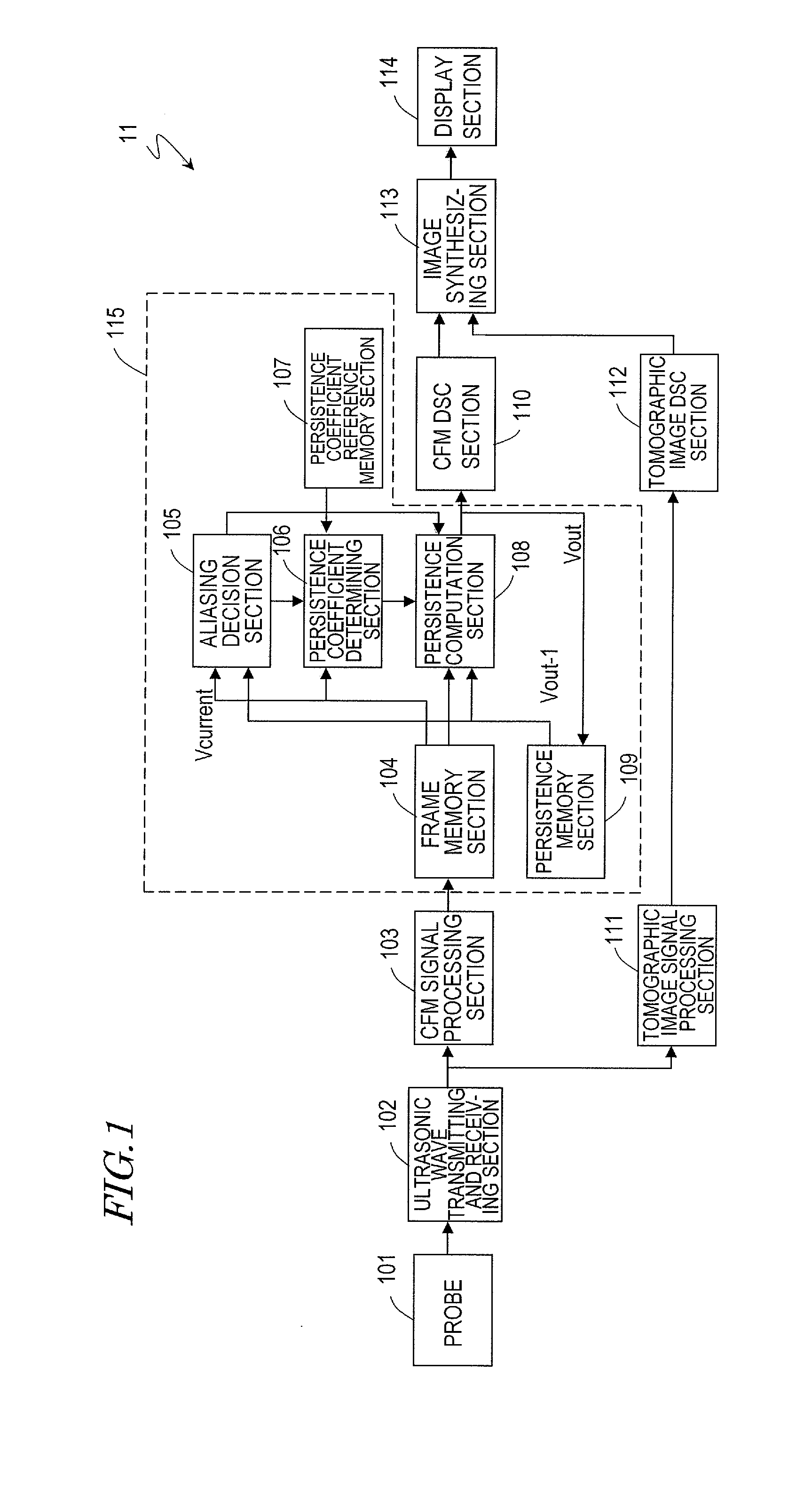
[0042]Hereinafter, a first preferred embodiment of an ultrasonic diagnostic apparatus according to the present invention will be described with reference to the accompanying drawings. FIG. 1 is a block diagram illustrating a first preferred embodiment of an ultrasonic diagnostic apparatus according to the present invention. The ultrasonic diagnostic apparatus 11 shown in FIG. 1 includes a probe 101, an ultrasonic wave transmitting and receiving section 102, a CFM signal processing section 103, a persistence processing 115, a tomographic image signal processing section 111, a CFM DSC section 110, a tomographic image DSC section 112, an image synthesizing section 113, and a display section 114. Among these components, the probe 101 and the display section 114 may be general-purpose ones and may be omitted from this ultrasonic diagnostic apparatus 11.

[0043]The ultrasonic wave transmitting and receiving section 102 generates a drive signal to drive the probe 101 and outputs the signal t...

embodiment 2

[0084]Hereinafter, a second preferred embodiment of an ultrasonic diagnostic apparatus according to the present invention will be described with reference to the accompanying drawings. FIG. 4 is a block diagram illustrating a second preferred embodiment of an ultrasonic diagnostic apparatus according to the present invention. The ultrasonic diagnostic apparatus 12 shown in FIG. 4 includes a probe 101, an ultrasonic wave transmitting and receiving section 102, a CFM signal processing section 103, a persistence processing 115′, a tomographic image signal processing section 111, a CFM DSC section 110, a tomographic image DSC section 112, an image synthesizing section 113, and a display section 114. Among these components, the probe 101 and the display section 114 may be general-purpose ones and may be omitted from this ultrasonic diagnostic apparatus 12.

[0085]As already described for the first preferred embodiment, the ultrasonic wave transmitting and receiving section 102 generates a ...


PUM


Abstract

An ultrasonic diagnostic apparatus according to the present invention includes: a transmitting and receiving section, which drives a probe repeatedly to send out ultrasonic waves toward a subject and which makes the probe receive reflected echoes produced by having the ultrasonic waves reflected by the subject, thereby generating received signals; a color flow mapping signal processing section for sequentially generating, based on the received signals, blood flow velocity data about a portion of each frame representing the blood flow of the subject; a persistence processing section for performing persistence processing on the blood flow velocity data of each frame; a tomographic image signal processing section for generating B-mode tomographic image frame data based on the received signals; and an image synthesizing section for synthesizing together the persistence-processed blood flow velocity data and the B-mode tomographic image frame data. The persistence processing section makes an aliasing decision based on the blood flow velocity data of the current frame and the persistence-processed blood flow velocity data of an earlier frame that precedes the current frame, and changes a persistence coefficient dynamically according to a result of the aliasing decision and based on those blood flow velocity data of the current and earlier frames.

Description

TECHNICAL FIELD[0001]The present invention relates to an ultrasonic diagnostic apparatus and more particularly relates to a technique for processing a persistence involved with color flow mapping.BACKGROUND ART[0002]An ultrasonic diagnostic apparatus sends out an ultrasonic wave toward a subject, receives its reflected echo, and then analyzes information included in the echo, thereby generating an image representing the subject's internal body tissue. For example, blood flowing through a subject's internal body tissue can also be represented as an image by so-called “color flow mapping” (which will be sometimes abbreviated herein as “CFM”). And ultrasonic diagnostic apparatuses that can indicate the blood flow status are used extensively in the entire field of medical treatment in general.[0003]Color flow mapping is also called “color Doppler imaging (CDI)”, which uses the Doppler effect. When blood flow is irradiated with an ultrasonic wave, its reflected echo will have a Doppler s...

Claims


Application Information

Patent Timeline
Patent Type & Authority Applications(United States)
IPC IPC(8): A61B8/14
CPCA61B8/13A61B8/06
Inventor MIGITA, MANABU
Owner KONICA MINOLTA INC
Why Eureka
Try Eureka