Heart valve prosthesis and method

a heart valve and prosthesis technology, applied in the field of heart valve prosthesis, can solve the problems of valve leaking, valve replacement, and death, and achieve the effects of reducing the risk of heart valve leaking and requiring valve replacemen

Active Publication Date: 2012-04-26
PERCUTANEOUS CARDIOVASCULAR SOLUTIONS
View PDF6 Cites 534 Cited by
  • Summary
  • Abstract
  • Description
  • Claims
  • Application Information

AI Technical Summary

Benefits of technology

[0031]In certain embodiments, the anchoring mechanism includes a plurality of primary prongs secured to and spaced about the housing body. The primary prongs are typically configured to engage native tissue of the heart outside of the native valve orifice.
[0032]The primary prongs may each be secured to the housing body by one or more legs extending from an end of the housing body.

Problems solved by technology

Heart valve regurgitation is a condition whereby the heart valve does not seal completely as a result of disease or injury, and may have fatal consequences.
Whilst valve stenosis can be treated by valvuloplasty (by balloon dilatation), this often results in the valve leaking and may require valve replacement.
Aortic valvuloplasty is generally not a very effective or durable treatment for aortic stenosis.
Surgical mitral valve replacement is quite invasive and cannot be performed on many sick patients with severe mitral regurgitation.
This procedure often results in resection of the anterior leaflet of the mitral valve which could lead to further left ventricular dysfunction.
Whilst there has been some success in developing replacement stent based aortic valve prostheses for delivery via percutaneous catheter-based methods, these techniques have not been particularly successful when applied to mitral valve prostheses.
Mitral valve replacement is firstly made difficult as a result of the anatomy of the mitral valve, and particularly that of the mitral valve annulus in which the mitral valve leaflets are located.
The mitral valve annulus is typically very distorted, and of unpredictable and non-uniform geometries, as compared to the relatively uniform aortic valve annulus.
This unpredictable anatomy makes it difficult to design a pre-constructed mitral valve prosthesis that would fit the mitral valve annulus in a satisfactory manner for safe, stable and meticulous deployment.
As a result, the mitral valve annulus cannot be subjected to any significant radial forces, as would be typical with an expanding stent type of valve prosthesis, as such radial forces would tend to collapse the aortic outflow tract, resulting in circulatory collapse with likely fatal consequences.
As such, stent type valve prostheses are presently generally not suitable for use as a replacement mitral valve.
This is a technically extremely challenging task associated with the potentially fatal complication of profound mitral regurgitation that may not be adequately addressed by the subsequent valve replacement.
The lack of an effective mitral valve may lead to overwhelming hemodynamic instability that may not be tolerated by the already compromised left ventricle and overwhelming pulmonary oedema may rapidly result.
Known stent based aortic valves are also not generally repositionable and therefore precise placement is difficult.
This could result in important structures such as the coronary arteries being compromised as a result.
Moreover, post-stenotic dilatation of the aorta may result in imprecise apposition of current stent based aortic valves, resulting in significant paravalvular leaks.
Current stent based aortic valves are also typically subject to fatigue and resultant fracture.
Further, various previously proposed replacement heart valve prostheses are relatively bulky and are thus not suited for percutaneous delivery using small diameter catheters, with more invasive larger catheters being required.

Method used


Image

  • Heart valve prosthesis and method
  • Heart valve prosthesis and method
  • Heart valve prosthesis and method

Examples


first embodiment

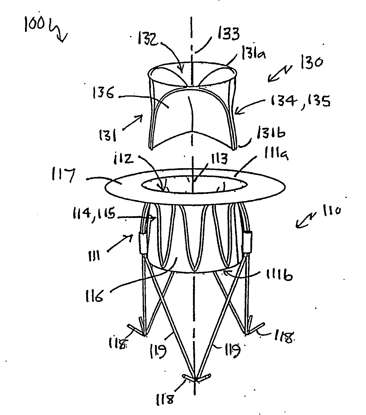
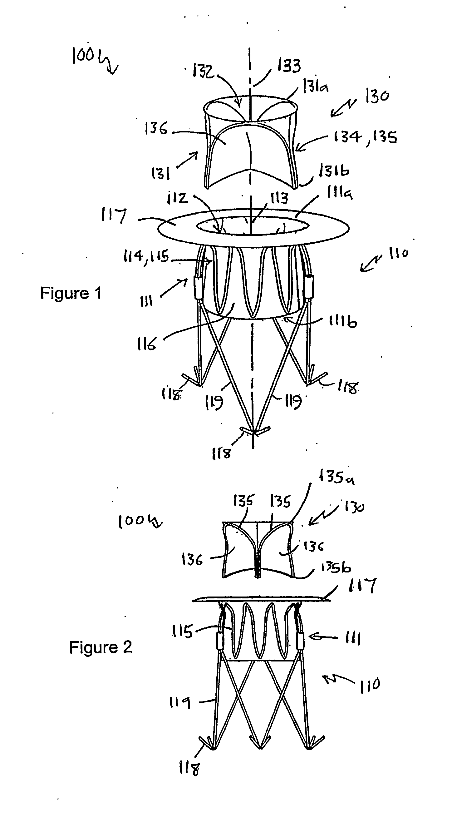
[0082]Referring to FIGS. 1 to 4 of the accompanying drawings, a heart valve prosthesis 100 is a two-component assembly, comprising a housing component 110 and a valve component 130. The heart valve prosthesis 100 is described here in terms of a mitral valve prosthesis for replacing a failed or failing mitral valve, however the heart valve prosthesis is also applicable to other heart valves including, in particular, the tricuspid valve.

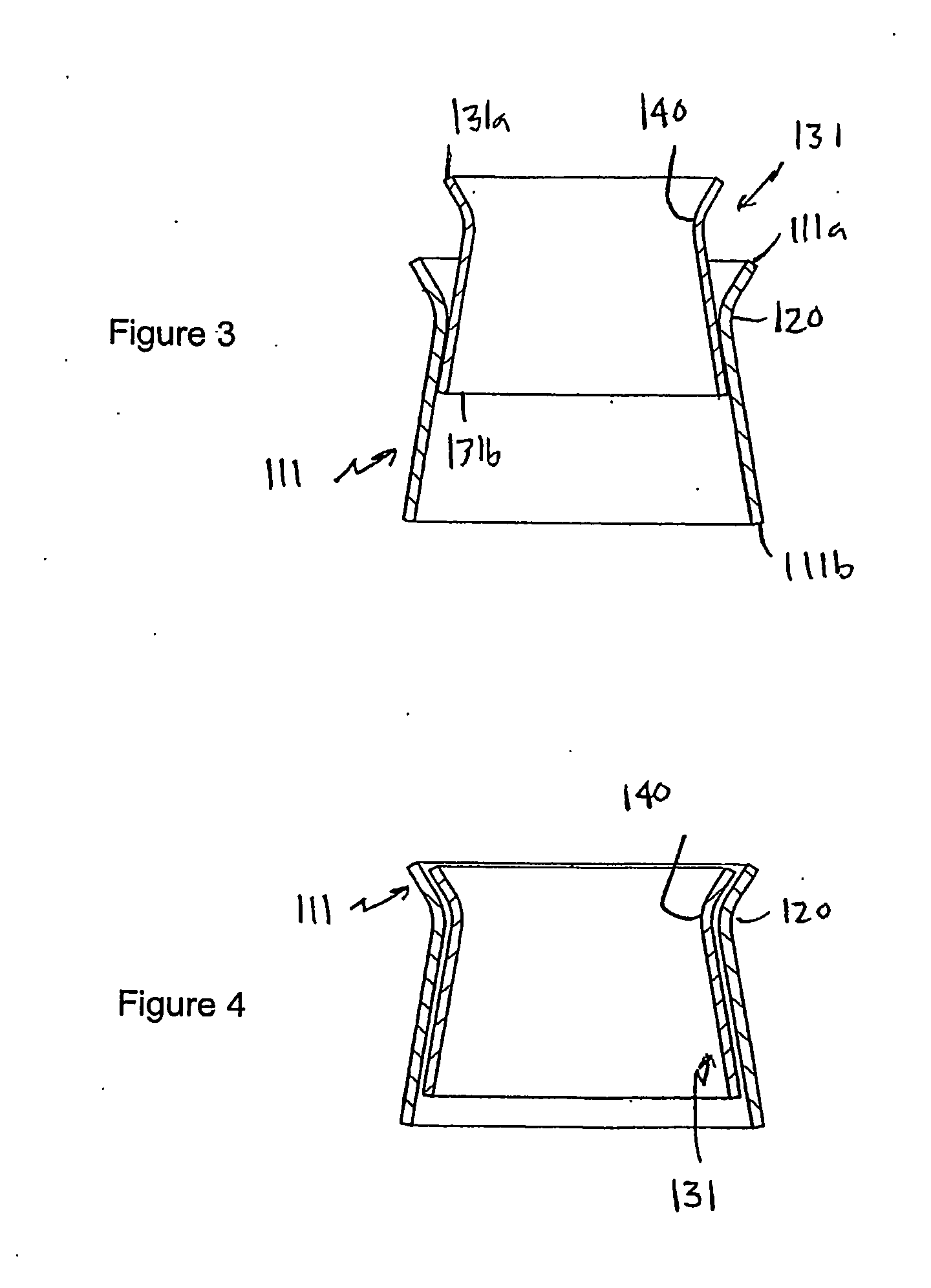
[0083]The housing component 110 includes a housing body 111 that has a housing body first end 111a, a housing body second end 111b, and a housing passage 112 extending between the housing body first and second ends 111a, 111b along a longitudinal housing axis 113. As will be discussed further below, the housing body 111 is configured to be located adjacent to and communicating with the native mitral valve orifice of the heart with the housing body second end 111b located within the left ventricle and the housing body first end 111a located adjacent to ...

fifth embodiment

[0123]Various other forms of securing the various heart valve prostheses described above are also envisaged. For example, the valve component may be configured with ventricular or atrial prongs to assist in directly fixing the valve component to the structure of the heart. The valve body and housing body may also be tapered so as to act as a plug that cannot migrate through the heart valve orifice, with an anchoring mechanism being located on that side of the valve orifice through which the narrower end of the housing body and valve body protrude. For example, with the heart valve prosthesis 500 of the fifth embodiment described above in relation to FIG. 22, the atrial end of both the valve body and housing body could be narrower than the valve orifice and the ventricular end of the valve body and housing body, with the anchor device 541 and anchor line 542 acting to retain the heart valve prosthesis partly within the heart valve orifice in a plugged state. In such an arrangement, t...

seventh embodiment

[0125]a two component heart valve prosthesis, in the form of an aortic heart valve prosthesis 600, and an associated aortic heart valve replacement procedure will now be described with reference to FIGS. 24 through 29.

[0126]Referring firstly to FIGS. 24 and 25, the housing component 610 of the aortic valve prosthesis 600 comprises a generally tubular housing body 611 that has a housing body first end 611a, a housing body second end 611b and a housing passage 612 extending between the housing body first and second ends 611a, 611b along a longitudinal housing axis 613. The housing passage 612 is double tapered, with the housing passage 612 being wider at the housing body first and second ends 611a, 611b than in the central neck region 620 of the housing passage 612. This double tapering of the housing passage 612 assists in positioning and retaining the valve component 630 as will be discussed further below. The housing component 610 is sized and shaped to be located within the ascend...


PUM


Abstract

A heart valve prosthesis (100) comprises a housing component (110) and a valve component (130). The housing component (110) comprises a housing body (111) having a housing passage (112) extending therethrough. The housing body (111) is configured to be located in, or adjacent to and communicating with, a native valve orifice (16) of a heart (10) and to engage structure of the heart (10) to fix the housing body (111) in relation to the valve orifice (161). The housing component (111) is collapsible for delivery via catheter (2). The valve component (130) comprises a valve body (131) having a valve passage (132) extending therethrough. The valve body (131) is configured to be fixed within the housing passage (112) with the valve passage (132) extending along the housing passage (112). One or more flexible valve elements (131) is/are secured to the valve body and extend across the valve passage (132) for blocking blood flow in a first direction through the valve passage (132) whilst allowing blood flow in the opposing direction. The valve component (130) is collapsible for delivery via catheter (2) separate to the housing component (110). An associated method of replacing a failed or failing heart valve utilising the heart valve prosthesis (100) is also disclosed.

Description

TECHNICAL FIELD[0001]The present invention relates to a heart valve prosthesis and associated method of treating a failed or failing heart valve. The invention is particularly related to a two-component heart valve prosthesis that is implantable by a two-step approach.BACKGROUND OF THE INVENTION[0002]Heart valve regurgitation is a condition whereby the heart valve does not seal completely as a result of disease or injury, and may have fatal consequences. Valve stenosis is a condition where the valve is narrowed and cannot open normally. Whilst valve stenosis can be treated by valvuloplasty (by balloon dilatation), this often results in the valve leaking and may require valve replacement. Aortic valvuloplasty is generally not a very effective or durable treatment for aortic stenosis.[0003]Malfunctioning heart valves have typically been replaced with mechanical or biologic heart valve prostheses using highly invasive open-heart surgical techniques. Surgical mitral valve replacement is...

Claims


Application Information

Patent Timeline
Patent Type & Authority Applications(United States)
IPC IPC(8): A61F2/24
CPCA61B17/0057A61B2017/00575A61B2017/0061A61F2/2418A61F2/2436A61F2/2457A61F2230/008A61F2250/006A61F2220/0008A61F2220/0016A61F2230/0054A61F2230/0078A61F2002/8486
Inventor THAMBAR, SUKUCOOK, MARTIN CHRISTOPHERSCHRECK, STEFANJAYASINGHE, STAYAJIT ROHAN
Owner PERCUTANEOUS CARDIOVASCULAR SOLUTIONS
Why Eureka
Try Eureka