Method for reducing vibration amplitudes

Inactive Publication Date: 2012-05-03
MTU AERO ENGINES GMBH
View PDF2 Cites 18 Cited by
  • Summary
  • Abstract
  • Description
  • Claims
  • Application Information

AI Technical Summary

Benefits of technology

[0033]A number of embodiments of the present invention have the advantage that instead of damping vibrations that have already been excited, the excitation of vibrations can be reduced. Whereas with conventional methods as described in

Problems solved by technology

Therefore, each individual vane is exposed to highly time-dependent forces.
In this resonance situation, high vibration amplitudes and corresponding mechanical stresses for the rotor disk, particularly

Method used


Image

  • Method for reducing vibration amplitudes
  • Method for reducing vibration amplitudes
  • Method for reducing vibration amplitudes

Examples


Embodiment Construction

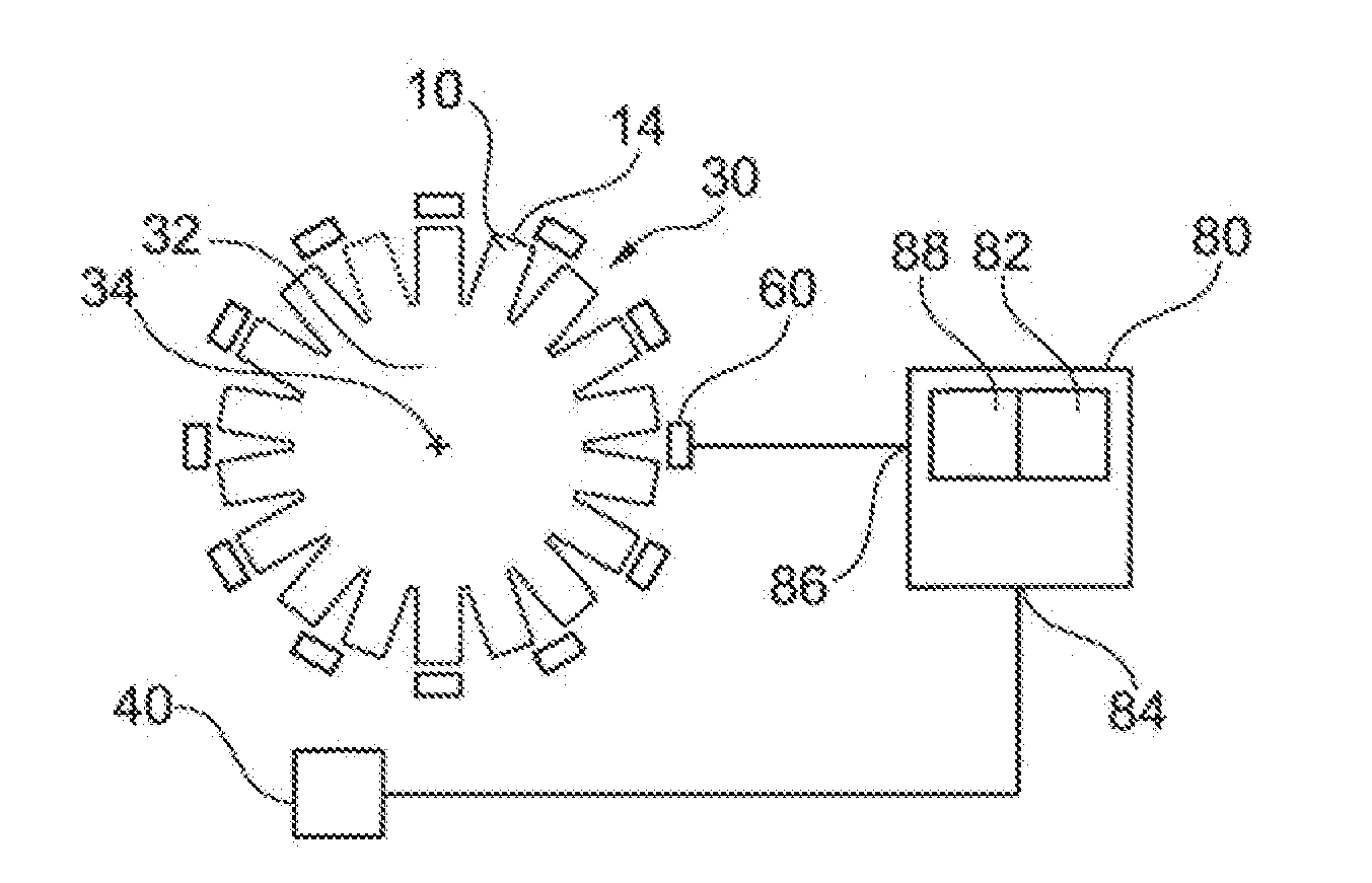
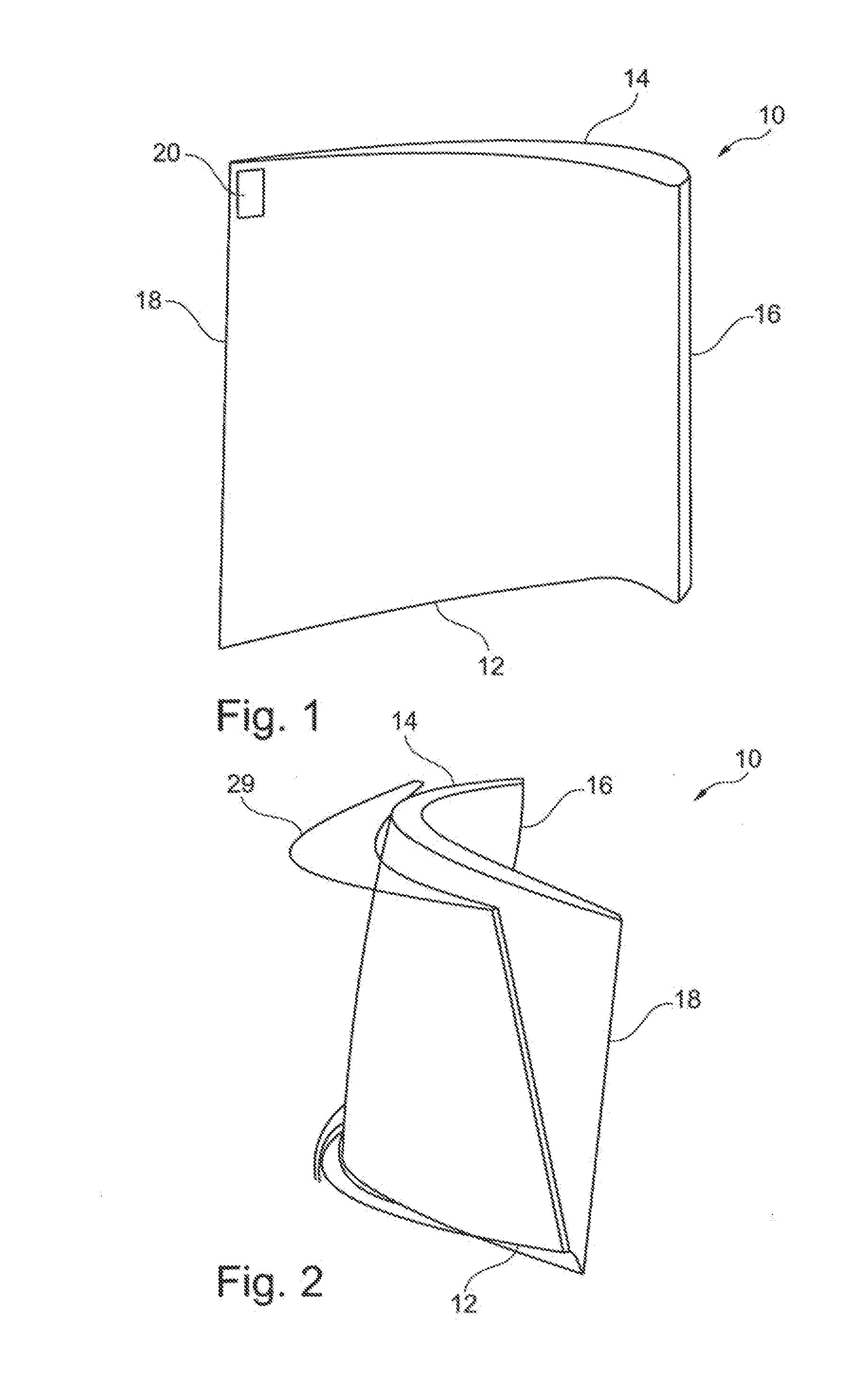
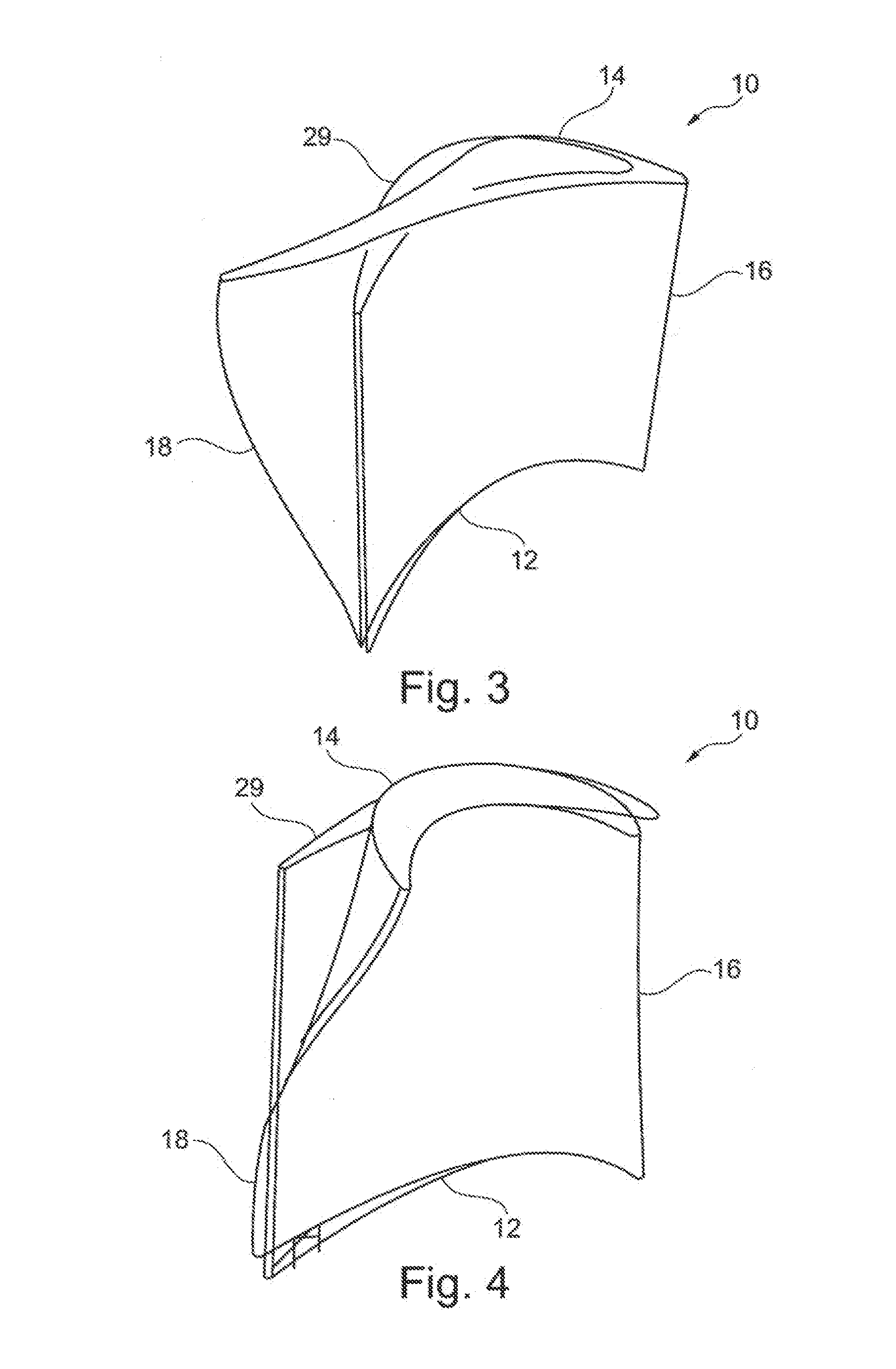
[0041]FIGS. 1 to 4 each show a schematic illustration of a blade 10 or a vane of a turbine blade. The blade 10 can be a component of a moving vane or of a rotor disk or of a rotor stage or of a guide vane or of a stator disk or of a stator stage. The illustrated blade 10 has no shroud band. However, the following embodiments can also be used with a moving blade that has a shroud band.

[0042]The blade 10 has a fixed end or attached end 12 and an unattached end 14. On the attached end 12, the blade 10 transitions across a platform to a blade root, for example. Platform, blade root, disk ridge, disk segment and other components of the blade or the turbine disk or the turbine stage are not shown in FIGS. 1 to 4. The blade 10 further has a leading edge 16 and a trailing edge 18. Also shown in FIG. 1 is a magnet 20 at the unattached end 14 near the trailing edge 18 of the blade 10, which will be described further below.

[0043]FIGS. 2 to 4 show schematic illustrations of snapshots of the bla...


PUM

PropertyMeasurementUnit
Temperatureaaaaaaaaaa
Forceaaaaaaaaaa
Pressureaaaaaaaaaa

Abstract

The English-language Abstract from the international application is to be retained and is therefore not duplicated in the specification.

Description

CROSS-REFERENCE TO RELATED APPLICATIONS[0001]This application is a U.S. National Phase application submitted under 35 U.S.C. §371 of Patent Cooperation Treaty application serial no. PCT / DE2010 / 000783, filed Jul. 7, 2010, and entitled METHOD FOR REDUCING VIBRATION AMPLITUDES, which application claims priority to German patent application serial no. DE 10 2009 032 549.2, filed Jul. 10, 2009, and entitled VERFAHREN ZUM MINDERN VON SCHWINGUNGSAMPLITUDEN.[0002]Patent Cooperation Treaty application serial no. PCT / DE2010 / 000783, published as WO 2011 / 003398, and German patent application serial no. DE 10 2009 032 549.2, are incorporated herein by reference.TECHNICAL FIELD[0003]The present invention relates to a method and a device for reducing the vibration amplitude of a structure that is capable of vibrating, which structure can be excited to vibration by an excitation force. Structures that are capable of vibrating are particularly stator and rotor vanes of axial compressors or turbines,...

Claims


Application Information

Patent Timeline
IPC IPC(8): B23P6/00B23P25/00
CPCF01D5/26F01D25/04F01D25/06Y10T29/49718Y02T50/673F05D2260/96Y10T29/51F04D29/668Y02T50/60
Inventor BORUFKA, HANS PETERARRIETA, HERNAN VICTORHARTUNG, ANDREASRETZE, ULRICH
Owner MTU AERO ENGINES GMBH
Why Eureka
Try Eureka