Empennage of a helicopter

a helicopter and empennage technology, applied in the direction of airflow influencers, fuselages, transportation and packaging, etc., can solve the problems of increasing noise from the back and sides of the helicopter, additional noise sources, and non-optimized shrouded tail rotors, so as to reduce the overall sound level of the empennage of the helicopter

Active Publication Date: 2014-03-13
AIRBUS HELICOPTERS DEUT GMBH
View PDF4 Cites 13 Cited by
  • Summary
  • Abstract
  • Description
  • Claims
  • Application Information

AI Technical Summary

Benefits of technology

[0018]It is an object of the invention to reduce the overall sound level of the empennage of a helicopter.

Problems solved by technology

It is a fact, that all anti-Torque Systems for helicopters produce noise additional to the noise of the main rotor.
For shrouded tail-rotors there might be additional sources of noise due to body resonances and cavity effects.
While the fan noise is shielded by the nacelle of the helicopter in flight direction, non-optimized shrouded tail-rotors emit still significant amounts of noise to the back and to the sides of the helicopter.
Berlin 1994” has shown that there are significant increases of noise levels for specific narrow frequency ranges, if the clearance is more than 0.003 times the rotor diameter.
Due to the increase of the number of fundamental frequencies and their harmonics, the noise of the tail structure of the helicopter is a kind of broad band noise which is able to excite a lot of body and cavity resonances.
However it is very difficult—if not impossible—to completely reduce the broad-band noise with stochastic frequencies as it results from the operation of the shrouded tail rotor.

Method used


Image

  • Empennage of a helicopter
  • Empennage of a helicopter
  • Empennage of a helicopter

Examples


Embodiment Construction

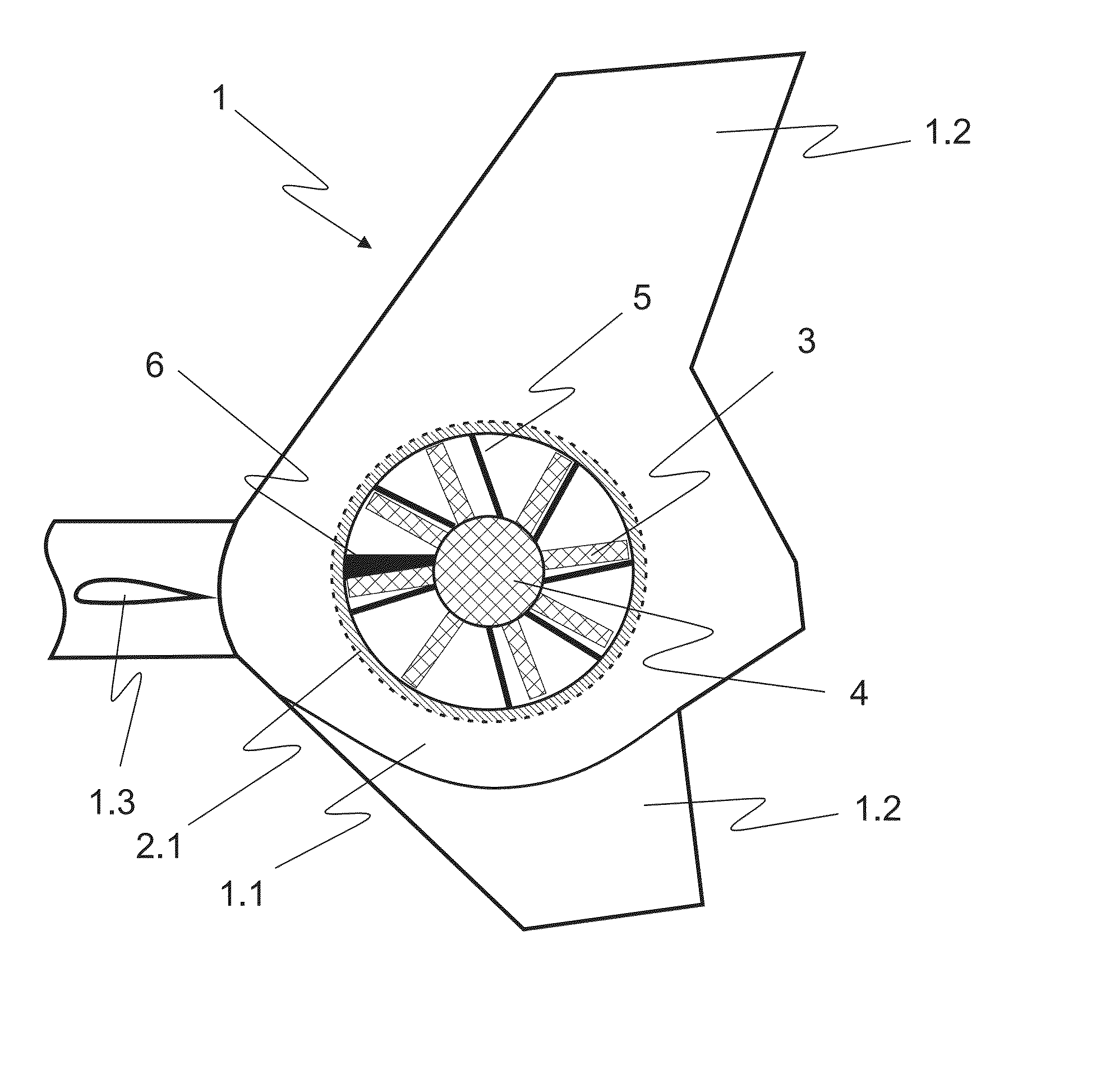
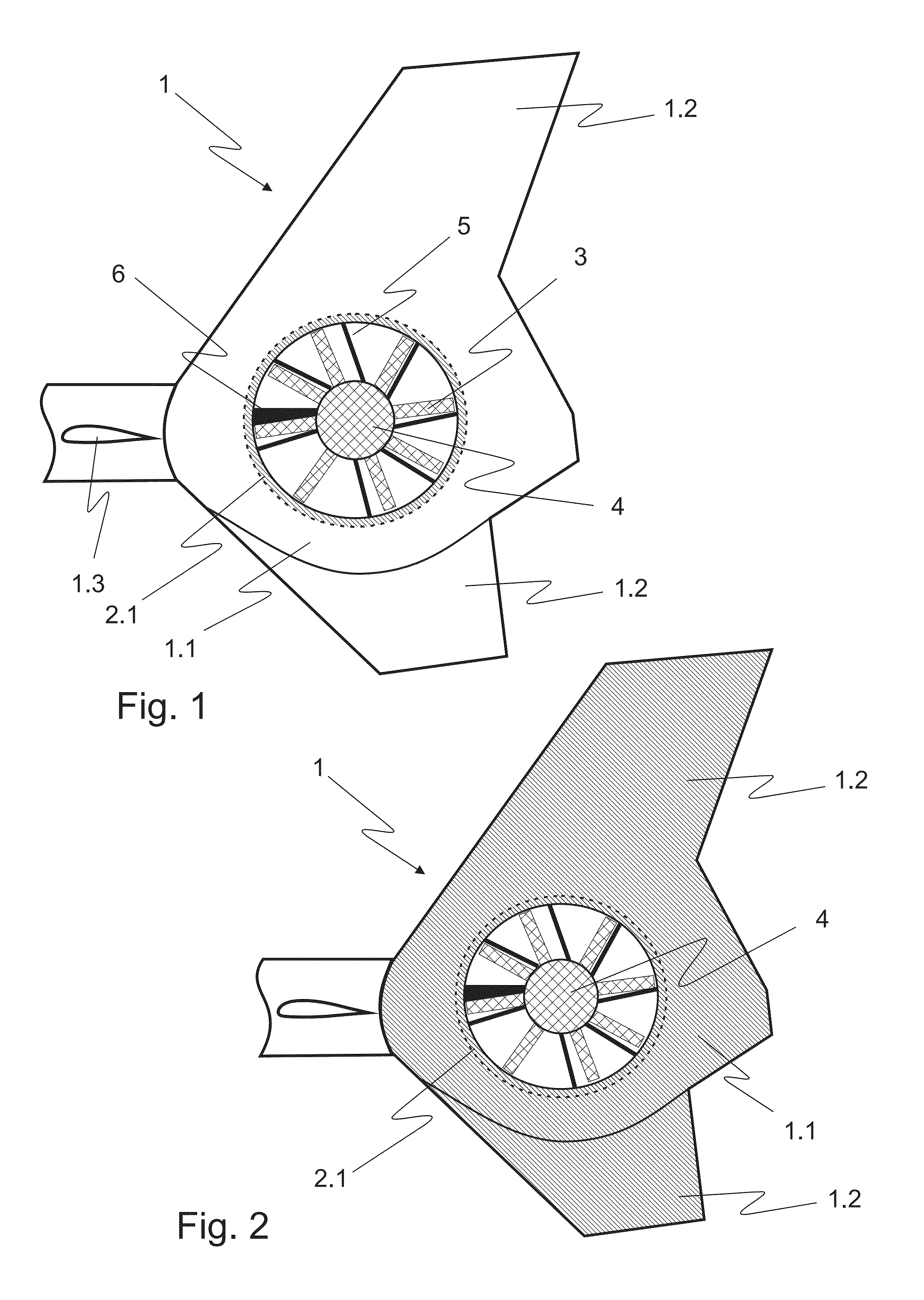
[0036]According to FIG. 1 a tail boom 1 of a helicopter has an empennage 1.1 comprising a ducted counter-torque device with a multi-blade rotor 4 with rotor blades 3 inside a shroud 2.1. The empennage 1.1 comprises furthermore shrouded vertical tail fins 1.2 for assisting in yaw control. The rotor 4 is actuated by an actuation shaft 6 mounted at the tail boom 1. Two horizontal stabilizers 1.3 are situated left and right to the tail boom 1 for pitch control. Flow-straightening stators 5 are positioned downstream from the rotor 4 inside the shroud 2.1. The flow-straightening stators 5 consist of stationary vanes disposed substantially in a star configuration parallel to the plane of rotor 4.

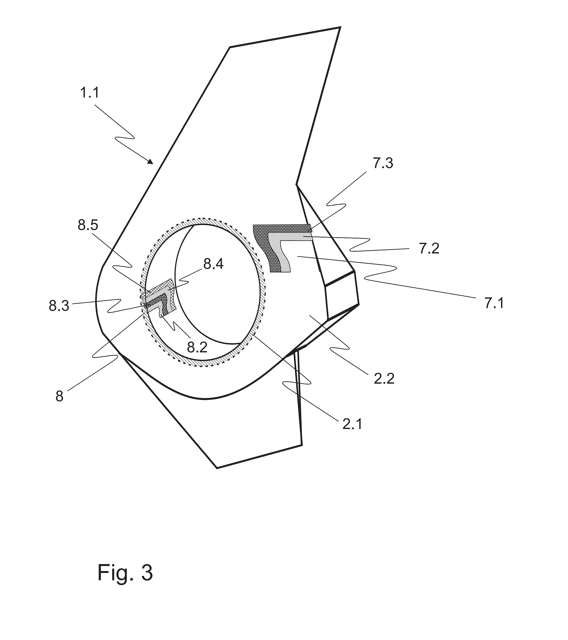
[0037]The shroud 2.1 containing the ducted tail rotor 4 is sheathed with a composite structure (cf. FIG. 5b) for damping vibrations and broad-band noise produced from the operating rotor 4.

[0038]According to FIG. 2 corresponding features are referred to with the references of FIG. 1. In addition to...


PUM


Abstract

An empennage (1.1) of a helicopter comprising a ducted counter-torque device with a multi-blade rotor (4) of rotor blades (3) and optional vertical tail fins (1.2). Flow-straightening stators (5) of stationary vanes are disposed substantially in a star configuration parallel to the rotor plane downstream from the rotor (4). A shroud (2.1) of the ducted counter-torque device is sheathed with a composite structure of an outer erosion protecting surface layer (7.1, 8.1) made of a hard plastic or a plastic composite material, and at least one succeeding layer (7.2, 8.2) of an elastomeric damping material.

Description

CROSS REFERENCE TO RELATED APPLICATIONS[0001]This application claims priority to European application No. EP 12 400037.3 filed Sep. 7, 2012, the disclosure of which is incorporated in its entirety by reference herein.BACKGROUND OF THE INVENTION[0002](1) Field of the Invention[0003]The invention is related to an empennage / fairing structure of a helicopter with a ducted counter-torque device with the features of the preamble of claim 1.[0004](2) Description of Related Art[0005]Shrouded anti-torque systems for helicopters consist essentially of an empennage structure including a shroud and a ducted fan with an airflow duct and a fan assembly coaxially mounted within the airflow duct. It is a fact, that all anti-Torque Systems for helicopters produce noise additional to the noise of the main rotor. While conventional rear rotors for helicopters are often complex, fragile, and require large rotor diameters, the faired / shrouded anti-torque rotors are smaller because of better aerodynamic ...

Claims


Application Information

Patent Timeline
Patent Type & Authority Applications(United States)
IPC IPC(8): B64C1/40B64C27/82
CPCB64C27/82B64C1/40B64C2027/8254B64C2027/8272B64C2027/8281B64D2045/009B64C5/06
Inventor KREITMAIR-STECK, WOLFGANGHEBENSPERGER, MICHAEL
Owner AIRBUS HELICOPTERS DEUT GMBH
Why Eureka
Try Eureka