Method of making a turbocharger housing

a technology of turbocharger and housing, which is applied in the direction of engine components, gas turbine plants, mechanical apparatus, etc., can solve the problems of difficult implementation of such turbocharger designs in sheet metal construction, increased manufacturing costs, and increased manufacturing costs, so as to improve the durability of the overall system, and ensure the effect of quality

Active Publication Date: 2012-05-03
BENTELER AUTOMOBILTECHNIK GMBH
View PDF11 Cites 11 Cited by
  • Summary
  • Abstract
  • Description
  • Claims
  • Application Information

AI Technical Summary

Benefits of technology

[0010]A method according to the present invention permits the realization of defined gap dimensions between a turbine wheel and an inner system of a turbocharger housing designed in sheet-metal construction. As a result, a turbocharger system can be manufactured with high precision and superior efficiency, even when constructed in lightweight configuration. Moreover, the performance is uniform and reproducible for a turbocharger line manufactured in series so that engines or vehicles equipped with such turbocharger housings operate with comparable efficiency.
[0011]Another benefit of the invention is the realization of a smallest minimum gap between the turbine wheel and the sheet-metal shell of the inner system, while preventing a contact of these components, so called rubbing, thus positively affecting the durability of the overall system.

Problems solved by technology

Turbochargers are exposed during operation to significant mechanical stress and in particular thermal stress.
Practice has shown, however, that the manufacture of such turbocharger designs in sheet-metal construction becomes very difficult to implement.
When producing sheet-metal housings through a forming process, such as e.g. deep-drawing or compression, the manufacturing tolerances are inadequate and become even greater as a result of thermal joining processes.
These fluctuations of the tolerances during manufacture of turbocharger housing in sheet-metal construction pose therefore a problem.

Method used


Image

  • Method of making a turbocharger housing
  • Method of making a turbocharger housing

Examples


Embodiment Construction

[0023]Throughout all the figures, same or corresponding elements may generally be indicated by same reference numerals. These depicted embodiments are to be understood as illustrative of the invention and not as limiting in any way. It should also be understood that the figures are not necessarily to scale and that the embodiments are sometimes illustrated by graphic symbols, phantom lines, diagrammatic representations and fragmentary views. In certain instances, details which are not necessary for an understanding of the present invention or which render other details difficult to perceive may have been omitted.

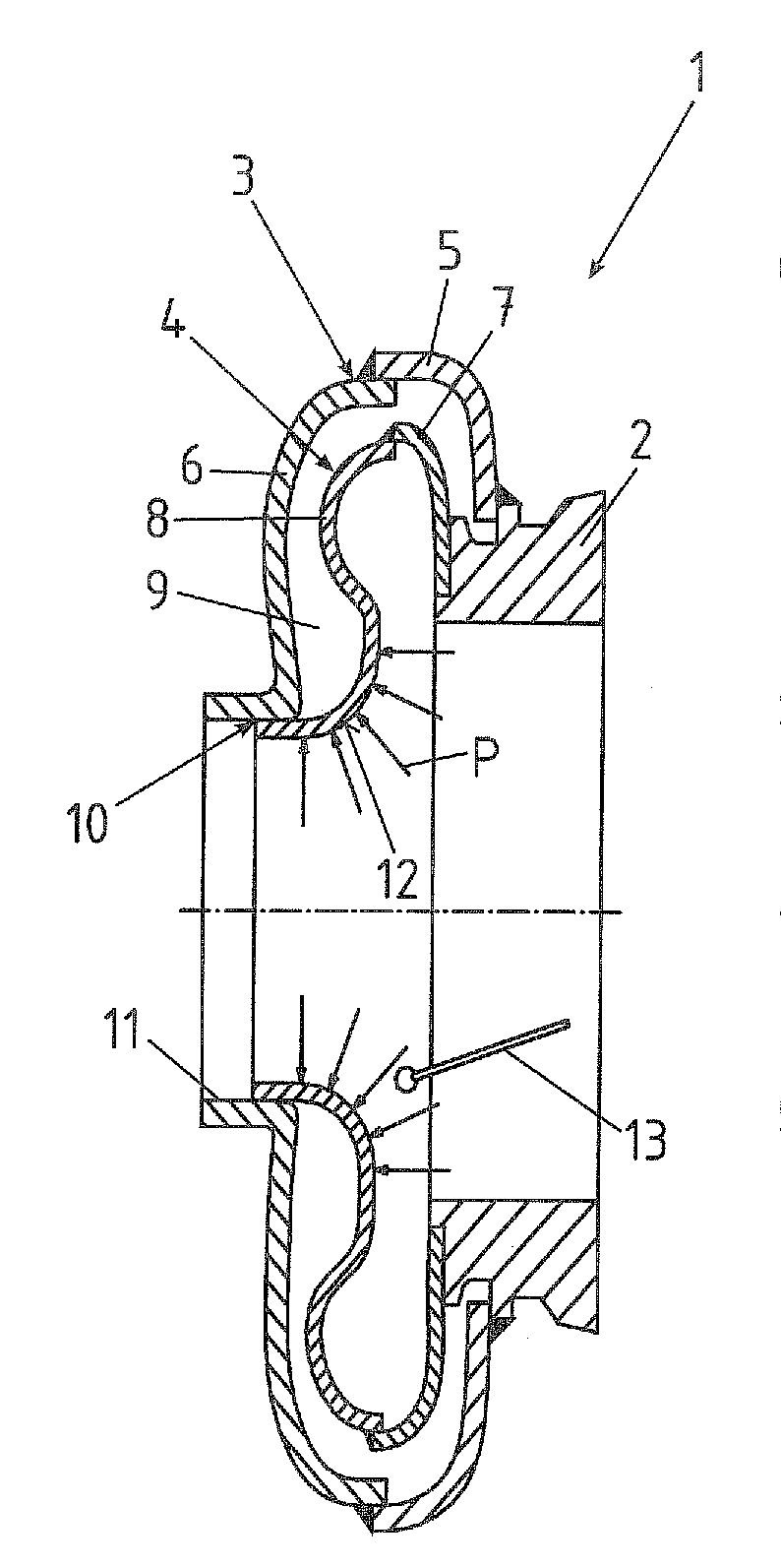
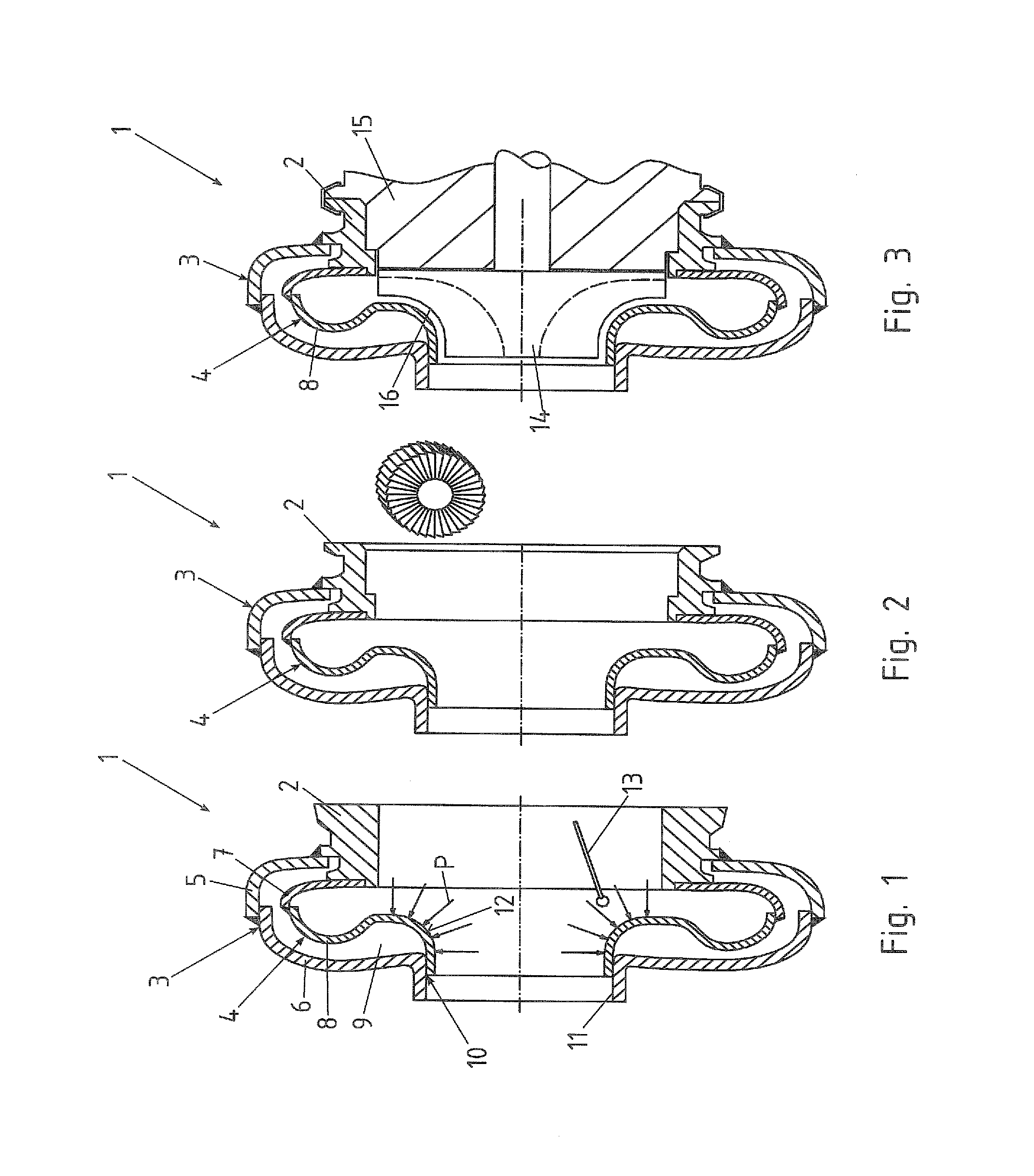
[0024]Turning now to the drawing, and in particular to FIG. 1, there is shown a cross section of a turbocharger housing, generally designated by reference numeral 1 and constructed in sheet-metal construction. The turbocharger housing 1 includes a supporting bearing flange 2 which is connected with an outer system 3 and an inner system 4. The outer system 3 and the inner sys...


PUM

PropertyMeasurementUnit
mechanical stressaaaaaaaaaa
thermal stressaaaaaaaaaa
weightaaaaaaaaaa

Abstract

In a method of making a turbocharger housing surfaces of a sheet-metal shell which bound a gap towards the turbine wheel are measured, after the sheet-metal shell has been joined with a bearing flange provided for support of a turbine wheel, to generate measuring values. Subsequently, the bearing flange is machined in dependence on the measuring values for establishing a position of the turbine wheel in relation to the bearing shell and thus of the sheet-metal shell.

Description

CROSS-REFERENCES TO RELATED APPLICATIONS[0001]This application claims the priority of German Patent Application, Serial No. 10 2010 019 404.2, filed May 4, 2010, pursuant to 35 U.S.C. 119(a)-(d), the content of which is incorporated herein by reference in its entirety as if fully set forth herein.BACKGROUND OF THE INVENTION[0002]The present invention relates to a method of making a turbocharger housing.[0003]The following discussion of related art is provided to assist the reader in understanding the advantages of the invention, and is not to be construed as an admission that this related art is prior art to this invention.[0004]Internal combustion engines for motor vehicle are increasingly charged through provision of a turbocharger in order to realize efficient fuel consumption. Turbochargers are exposed during operation to significant mechanical stress and in particular thermal stress. At the same time the weight of such an assembly should be as small as possible so as not to adv...

Claims


Application Information

Patent Timeline
Patent Type & Authority Applications(United States)
IPC IPC(8): B23P15/00
CPCF05D2230/10F02C6/12F05D2220/40Y10T29/49243F01D9/026Y10T29/49236Y10T29/49995Y10T29/49861B23P15/00F01D25/24Y10T29/49323Y10T29/4932F01N13/143
Inventor SMATLOCH, CHRISTIANGRUSSMANN, ELMARARLT, FRANK
Owner BENTELER AUTOMOBILTECHNIK GMBH
Why Eureka
Try Eureka