Assembly for Fastening a Plurality of Solar Modules to a Building Roof or a Building Facade and Clip for Forming a Stop Element on a Surface

Inactive Publication Date: 2012-05-03
ENERGIEBURO AG
View PDF10 Cites 26 Cited by
  • Summary
  • Abstract
  • Description
  • Claims
  • Application Information

AI Technical Summary

Benefits of technology

[0040]For embodiments of the assembly in case of which the insertion elements mentioned above are used and the clamping elements are each secured against longitudinal shifting along the carrier profile by targeted plastic deformation of a profile section of the carrier profile and/or of the ridge element, it is preferred that, for securing the clamping elements, at least one of the insertion elements, particularly an insertion metal sheet or an insertion metal plate, is present, which is hindered to shift longitudinally along the carrier profile by the plastic deformation of the profile section of the carrier profile and/or the insertion element and makes impossible a longitudinal shift of the clamping element along the carrier profile. This may be particularly advantageous depending on the assembling situation.
[0041]In yet a further preferred embodiment of the assembly the carrier profile rows are each formed by multiple carrier profile pieces which are mutually spaced in longitudinal direction. By this, ma

Problems solved by technology

In case of the first emerging fastening systems, the solar modules were screwed by means of fastening clips or fastening angles formed on them directly onto the installation surface or onto a subordinate construction created on the installation surface, this being a relatively work intense and at least a dangerous action on steep roofs, because it required a repeated handling of the cumbersome and at the same time fragile solar modules.
However, this fastening system has the disadvantage that a plurality of individual components is necessary, resulting in the fact that the installation is exacerbated in practical use.
Additionally, in case of this fastening system, the disadvantage arises that the delimiting edges of the solar modules are clamped between the carrier profiles and the clamping profiles in order to fasten the solar modules, such that a thermal expansion of the solar modules is hindered and it may come to a detaching of the fastenings or to a “migration” of the solar modules in the fastenings respectively, as a result of thermal stress.
In case of this fastening system a handling of the solar modules is only needed for inserting them, this significantly reducing the installation effort as well as the danger of damage of the solar modules or of a work accident.
A fastening of the solar modules onto the carrier profiles with delimiting edges running transversely with respect to the carrier profiles, as it may for example be desirable in case of steep roofs in order to be able to grant a stable fastening of the solar modules in an upright format, such that an assembly of the photovoltaically inactive connection section of the solar modules in the main fouling zone at its bottom edge running parallel to the eaves becomes possible, is however not possible with this system.
By this system a fastening of the solar modules onto the carrier profiles

Method used


Image

  • Assembly for Fastening a Plurality of Solar Modules to a Building Roof or a Building Facade and Clip for Forming a Stop Element on a Surface
  • Assembly for Fastening a Plurality of Solar Modules to a Building Roof or a Building Facade and Clip for Forming a Stop Element on a Surface
  • Assembly for Fastening a Plurality of Solar Modules to a Building Roof or a Building Facade and Clip for Forming a Stop Element on a Surface

Examples


Example

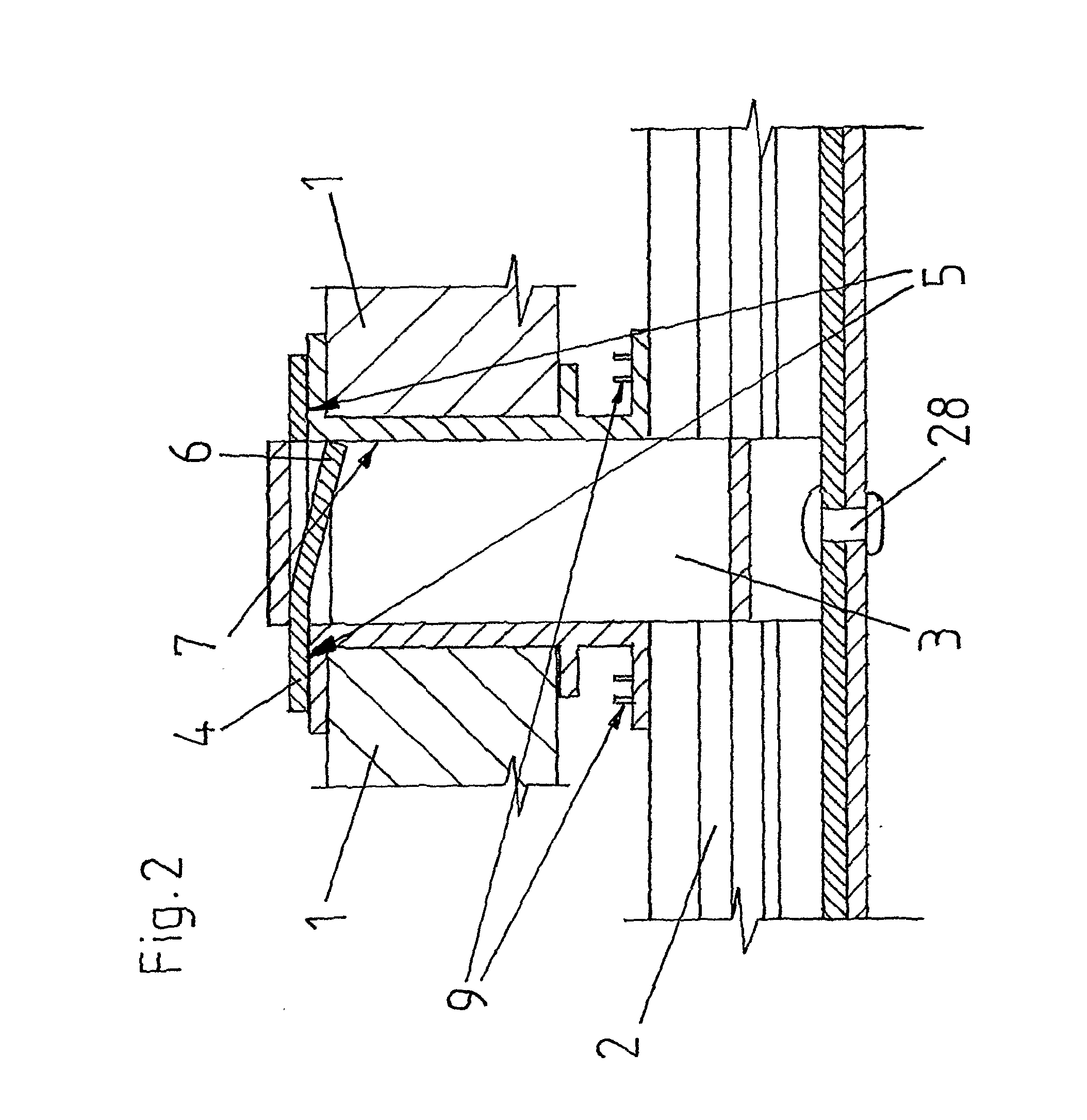
[0107]FIGS. 11 to 13 show a first embodiment according to the invention of a clip 9, as it is used in the assemblies of FIGS. 3 and 7, once in a side view (FIG. 11), once in a top view (FIG. 12) and once in another intended assembly situation than in FIGS. 3 and 7 (FIG. 13).

[0108]As one can see in FIG. 13, the clip 9 is suitable for forming a stop element on an outer surface 11 of an even, thin-walled, plate-shaped component 10 by attaching the clip in an opening 13, which is particularly round, rectangular or in the shape of an elongated hole, arranged in this outer surface 11, protruding through the component 10 and ending in a second outer surface 18 of the component 10, which is substantially parallel to the first outer surface 11.

[0109]The clip 9 is formed in one piece out of a punched part of stainless steel with uniform material strength and has two arm sections 15a, 15b which are connected to each other in a springy way by a spring section 14, their free ends being spaced re...

Example

[0120]FIGS. 19 and 20 show a third embodiment of a clip 9 according to the invention, once in a side view (FIG. 19) and once in a top view (FIG. 20). This clip 9 differs from the clip shown in FIGS. 11 to 13 substantially in that it has embossments 29 protruding towards the outside in the areas where it is typically gripped between forefinger and thumb for the installation or the disassembly respectively, by this increasing its grip. Additionally, this area is placed deeper here than the one in the assembly of FIGS. 11 to 13, such that the handling of the clip 9 during the installation and assembly is further enhanced because in the intended installed state this area of the clip 9 protrudes from the surface 11 of the component, on which it forms an abutment. A further difference to the clip shown in FIGS. 11 to 13 consists in that here the arm sections 15a, 15b have each on their upper side a cavity 30 such that they each form two separate contact surfaces 16. By this cavity 30, the...


PUM

PropertyMeasurementUnit
Thicknessaaaaaaaaaa
Forceaaaaaaaaaa
Angleaaaaaaaaaa

Abstract

The invention relates to a fastening assembly for solar modules (1), wherein the solar modules (1) are fastened to carrier profiles (2) arranged in several rows by way of clamping elements (3, 4) in that each clamping element (3, 4) extends over the mutually opposing delimiting edges of two solar modules (2), which run transversely to the carrier profile (2) and adjoin the clamping element (3, 4) on both sides. Each clamping element (3, 4) comprises a ridge element (3) and a head element (4) designed separate therefrom. The ridge element (3) is designed as a profile section and attached at the lower end thereof to the carrier profile (2) through insertion into profile contours of the carrier profile. The head element (4) is attached to the ridge element (3) in the region of the upper end of said element by being inserted into profile contours of the ridge element (3). To this end, the head element (3) protrudes beyond the ridge element (3) on both sides in the profile longitudinal direction of the ridge element (3) so as to extend over the delimiting edges of the solar modules (1) to be fastened. The invention provides a fastening system which comprises few components (2, 3, 4) that can be produced cost-effectively and enables the simple and secure fastening of solar modules (1) even under difficult ambient conditions by using delimiting edges that run transversely to the carrier profiles (2).

Description

BACKGROUND[0001]The invention is related to an assembly for fastening a plurality of solar modules for assembling a solar array on a building, to a clip for forming a stop element on an outer surface of an even, thin-walled plate-shaped component by fastening the latter in an opening arranged in this outer surface as well as a method for forming a stop element on an even outer surface of a thin-walled component by using the clip according to the preambles of the independent claims.PRIOR ART[0002]Different fastening systems have been known for attaching solar modules (also referred to as solar elements) on building roofs in order to assemble solar arrays.[0003]In case of the first emerging fastening systems, the solar modules were screwed by means of fastening clips or fastening angles formed on them directly onto the installation surface or onto a subordinate construction created on the installation surface, this being a relatively work intense and at least a dangerous action on ste...

Claims


Application Information

Patent Timeline
IPC IPC(8): E04D13/18B23P11/00F16B2/20H01L31/048
CPCF24J2/5205F24J2/5256F24J2002/4661F24J2002/4665F24J2002/5288Y02B10/12Y10T29/49826Y02E10/47Y02E10/50H02S20/00H02S20/23Y10T24/44017Y02B10/20F24S25/33F24S25/634F24S2025/018F24S2025/6002F24S2025/6004Y02B10/10
Inventor MEIER, CHRISTIANLANGENSKIOLD, ERIC
Owner ENERGIEBURO AG
Why Eureka
Try Eureka