
System and method for microplate pressurization

a microplate and pressurization system technology, applied in chemical methods analysis, laboratory glassware, instruments, etc., can solve the problems of reducing the power and size of the high pressure pump needed for pressurization, and reducing so as to reduce the size of the pressurizing equipment, reduce the amount of elasticity in many polymeric materials, and reduce the effect of high pressure processing

Active Publication Date: 2012-05-03
PRESSURE BIOSCI
View PDF5 Cites 2 Cited by
  • Summary
  • Abstract
  • Description
  • Claims
  • Application Information

AI Technical Summary

Benefits of technology

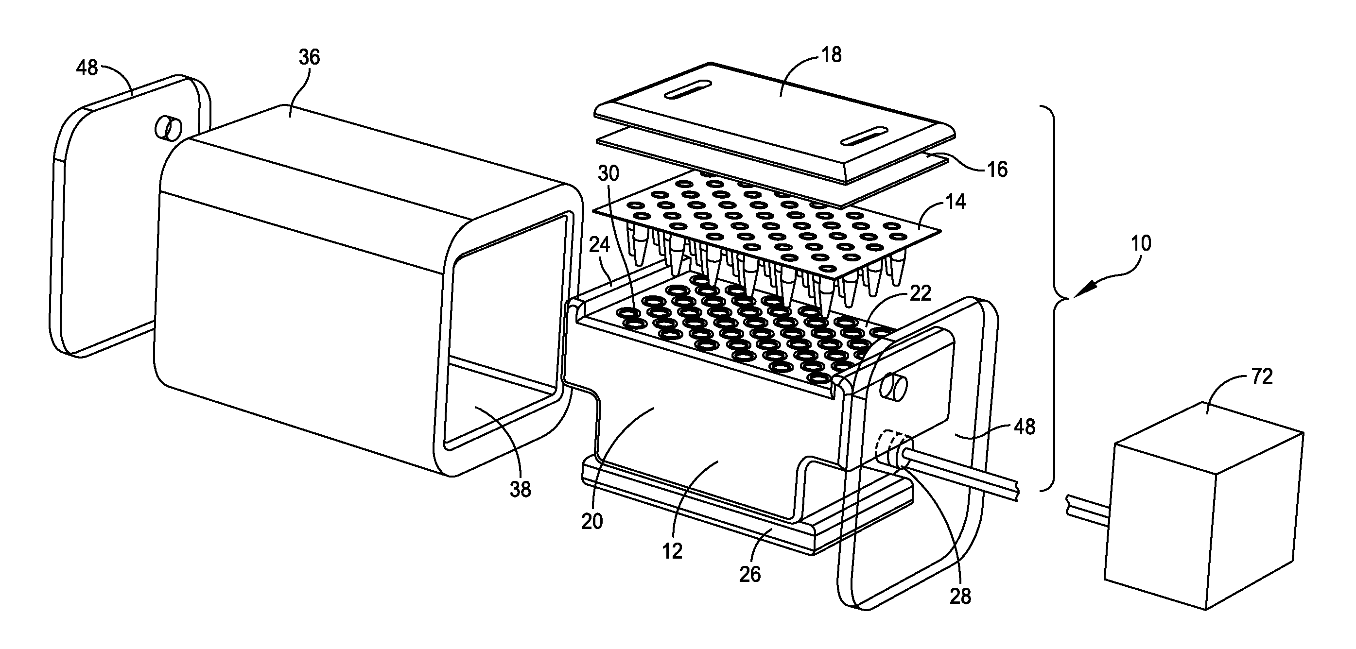
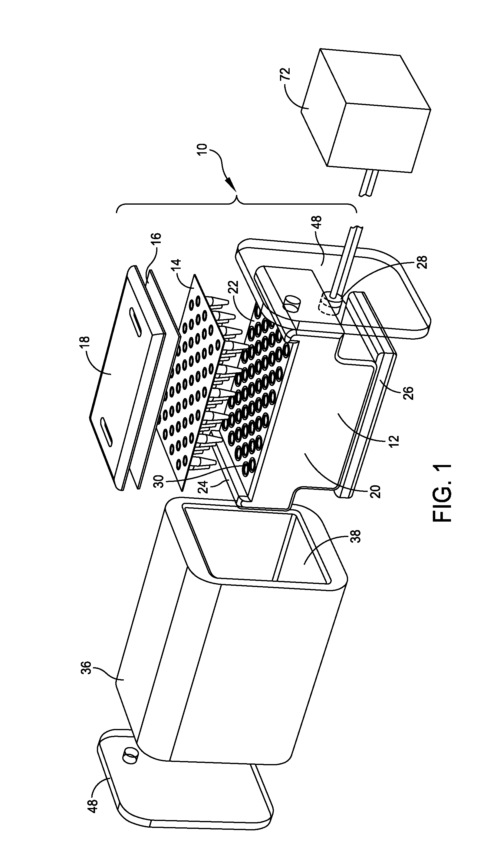
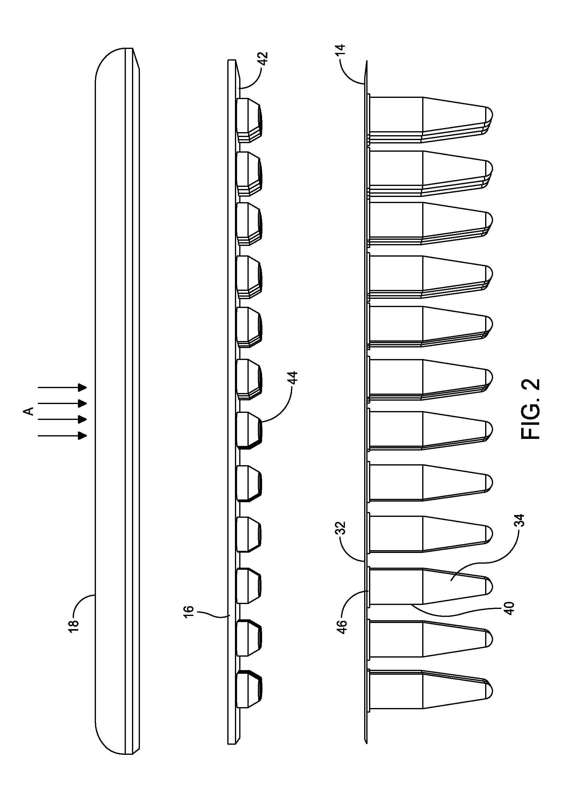
[0013]The present disclosure greatly reduces the size of the pressurizing equipment needed for high pressure processing. This is accomplished by creating small individual pressure chambers for each sample. Pressurizing fluid is communicated to each pressurizing chamber, and the applied pressure is transmitted though the elastic wall of the sample well. Because most fluids of interest are fairly incompressible, the amount of elasticity in many polymeric materials is sufficient to allow each filled tube to compress without resulting in its failure. In effect, 96, 48, or any number of samples can be processed in parallel, at the same time. By maintaining standard inter-well spacing, compatibility with downstream equipment will be maintained. The close fitting individual chambers allow the apparatus to use a minimum amount of pressurizing energy. This reduces the pressurization time and reduces the power and size of the high pressure pump needed for pressurization. In order to seal each tube sitting in its chamber, each tube is capped securely and each cap held in place. This can be accomplished by using a high clamping generated by a hydraulic lift, such as a foot, built into the carrier body.

Problems solved by technology

This reduces the pressurization time and reduces the power and size of the high pressure pump needed for pressurization.

Method used


Image

  • System and method for microplate pressurization
  • System and method for microplate pressurization
  • System and method for microplate pressurization

Examples


Embodiment Construction

[0031]Some aspects of the disclosure involve methods and systems for pressurizing a sample or sample mixture as well as to components thereof that facilitate exposing at least a portion of the sample to a pressurized condition. Pressurization of the sample mixture can involve exposing at least a portion of the sample to a pressure environment that differs from ambient. Pressurization can also involve, in some implementations of the disclosure, exposing at least a portion of the sample mixture to a plurality of pressurized environments or conditions.

[0032]One or more aspects of the disclosure can be directed to a sample pressurization system. The pressurizable sample system can comprise a microplate typically having a planar plate surface and at least one well which contains the sample to be pressurized. The sample pressurization system typically further comprises a carrier body having a receiving surface, at least one pressurizing fluid port, at least one fluid channel fluidly conne...


PUM

PropertyMeasurementUnit
volumesaaaaaaaaaa
pressuresaaaaaaaaaa
pressuresaaaaaaaaaa

Abstract

A pressurizable sample system includes a microplate having a planar plate surface and several sample wells. Each sample well has a flange positioned circumferentially around an outer surface of the sample well and against the planar plate surface. The sample system further includes a capping plate with a planar cap surface and several caps projecting from the planar cap surface. Each cap has a geometrical configuration in complementary correspondence with the configuration of the sample well.

Description

CROSS-REFERENCE TO RELATED APPLICATIONS[0001]This application claims priority under 35 U.S.C. §119(e) to U.S. Provisional Application Ser. No. 61 / 407,729 entitled “SYSTEM AND METHOD FOR MICROPLATE PRESSURIZATION,” filed on Oct. 28, 2010, which is incorporated herein by reference in its entirety.BACKGROUND OF THE INVENTION[0002]1. Field of Disclosure[0003]This disclosure relates to systems and methods of preparing a sample and, in particular, to systems and methods of pressurizing a sample or group of samples in an inter-well format compatible with the life science industry's standard 4.5 or 9 millimeter (mm) microplate to prepare the sample for further analytical procedures.[0004]2. Discussion of Related Art[0005]Advancements in chemical and biological analysis have been driven by analytical and separation equipment. However, the first step in analytical processes, sample preparation, has received little attention and has predominantly focused on off-line traditional mechanical shea...

Claims


Application Information

Patent Timeline
Patent Type & Authority Applications(United States)
IPC IPC(8): G01N1/28B01L3/00
CPCB01L3/50851B01L3/50853B01L9/50G01N1/28B01L2200/021B01L2200/0631B01L2400/0487B01L2200/0689B01L2200/141B01L2300/042B01L2300/048B01L2300/123B01L2300/14B01L2200/0678
Inventor TING, EDMUND Y.LAZAREV, ALEXANDER
Owner PRESSURE BIOSCI
Learn More