Cooling system

a cooling system and internal combustion engine technology, applied in the direction of machines/engines, mechanical equipment, transportation and packaging, etc., can solve the problems of not being able to dissipate heat from the shaft, affecting the operation state, and affecting the operation of the engine, so as to improve the warm-up behavior of the internal combustion engine, improve the warm-up behavior, and bring the required operating temperature faster

Active Publication Date: 2012-05-03
FORD GLOBAL TECH LLC
View PDF7 Cites 34 Cited by
  • Summary
  • Abstract
  • Description
  • Claims
  • Application Information

AI Technical Summary

Benefits of technology

[0014]The inventors herein have recognized the issues with the above approaches and provide an engine system to at least partly address them. In one embodiment, an internal combustion engine comprises a cabin heat exchanger circuit including a connecting line opening on an inlet side into a cylinder block coolant jacket, a main coolant pump arranged in the cabin heat exchanger circuit, an auxiliary coolant pump arranged in the connecting line, and a check valve.

Problems solved by technology

An operating state which is particularly difficult to manage for this reason is the rapid shutdown of the internal combustion engine from an operating state involving a high load.
The supply of lubricant is interrupted when stopping, and the dissipation of heat from the shaft is no longer assured.
The result is overheating of the lubricating oil and associated carbonization of the lubricating oil remaining in the exposed parts of the bearing assembly owing to the continued heating of the shaft caused by the hot turbine.
Ultimately, the carbonization of the lubricating oil leads to fouling of the rotor bearings and this frequently causes damage to the turbocharger.
Thus, the “no-flow strategy”, for example, is abandoned owing to the high coolant temperature even though the cylinder liners, for example, have still not heated up and are therefore virtually cold.

Method used


Image

  • Cooling system
  • Cooling system
  • Cooling system

Examples


Embodiment Construction

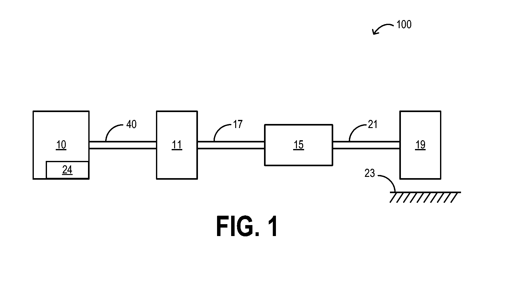
[0022]FIG. 1 shows a vehicle system 100 including internal combustion engine 10 coupled to torque converter 11 via crankshaft 40. Engine 10 may be a gasoline engine. In alternate embodiments, other engine configurations may be employed, for example a diesel engine. Engine 10 may be started with an engine starting system 24, including a starter, and one or more starter gears. In one example, the starter may be motor-driven (e.g. battery-driven or capacitor driven). In another example, the starter may be a powertrain drive motor, such as a hybrid powerplant connected to the engine by way of a coupling device. The coupling device may include a transmission, one or more gears, and / or any other suitable coupling device. The starter may be configured to support engine restart at low non-zero engine speeds, such as, for example at or below 50 rpm. Alternatively, the engine may be restarted in a low speed range, for example between 50 to 100 rpm. Alternatively, the engine may be restarted i...


PUM


Abstract

A cooling system for an engine is provided. In one embodiment, an internal combustion engine comprises a cabin heat exchanger circuit including a connecting line opening on an inlet side into a cylinder block coolant jacket, a main coolant pump arranged in the cabin heat exchanger circuit, an auxiliary coolant pump arranged in the connecting line, and a check valve. In this way, additional cooling and / or heating may be provided to the engine and associated components by the auxiliary coolant pump.

Description

RELATED APPLICATIONS[0001]The present application claims priority to German Patent Application No. 102010060319.8, filed on Nov. 3, 2010, the entire contents of which are hereby incorporated by reference for all purposes.FIELD[0002]The disclosure relates to an internal combustion engine which has a coolant circuit.BACKGROUND AND SUMMARY[0003]Conventional cooling systems have at least one head coolant jacket, one block coolant jacket, a main coolant pump that frequently is a mechanical pump, an auxiliary coolant pump that frequently is an electric pump, a radiator, a thermostat, a heat exchanger, a vapor separator, and further components and corresponding connecting lines. Below a specific coolant temperature of, for example, 90° C., the coolant flows through the main coolant pump, the coolant jackets, the heat exchanger, the oil cooler, the vapor separator and the thermostat, i.e. through the “small cooling circuit”. Once the specific temperature has been reached, the thermostat ope...

Claims


Application Information

Patent Timeline
Patent Type & Authority Applications(United States)
IPC IPC(8): F01P7/00B60H1/00
CPCF01P3/02F01P11/029F01P2060/12F01P2005/105F01P2060/08F01P2003/028
Inventor MEHRING, JANKUHLBACH, KAI SEBASTIANSTEINER, BERNDTOBERGTE, MICHAELQUIX, HANS GUENTER
Owner FORD GLOBAL TECH LLC
Why Eureka
Try Eureka