Pneumatic tire

a pneumatic tire and tread technology, applied in the field of pneumatic tires, can solve the problems of reducing the rigidity of the tread, affecting the steering stability and braking ability, and limited water absorption effect of the tread, so as to achieve the effect of enhancing the width of the cut, enhancing the braking performance on ice, and increasing the water absorption and discharging function

Active Publication Date: 2012-05-03
THE YOKOHAMA RUBBER CO LTD
View PDF8 Cites 1 Cited by
  • Summary
  • Abstract
  • Description
  • Claims
  • Application Information

AI Technical Summary

Benefits of technology

[0004]The present technology provides a pneumatic tire configured so that braking performance on ice is enhanced in a tire having sipes formed in a tread surface thereof.
[0011]According to the present technology, a pneumatic tire includes a closed sipe in a land portion formed in a tread surface, provided with at least three cuts extending in a radiation direction from an imaginary axis that extends in a depth direction of the land portion, and that terminate in the land portion. A widened portion where a width of a cut is locally increased is formed at least one position of an intermediate region from the imaginary axis to a terminating portion of the cuts. Therefore, due to the tread contact pressure caused by the tire contacting the ground, when traveling on icy road surfaces, the cuts open widely in a width direction centered on the widened portion, thus facilitating the flow of water on the icy road surface to the widened portion. The water that flows into the widened portion is efficiently dispersed toward the cuts and, therefore, water absorption and discharging functions can be advanced and braking performance on ice can be enhanced.

Problems solved by technology

However, if an excessive number of sipes are disposed in the tread surface, tread rigidity will decline, leading to steering stability and braking ability being negatively affected.
However, with this proposal, it is difficult to ensure tread rigidity due to a disposal spacing of the sipes being excessively narrow and, even if the disposal spacing of the sipes is increased, because the width of the cuts of the sipes is formed equally with respect to the longitudinal direction, when the tread surface contacts the ground, the sipes will not open sufficiently, leading to the water absorption effect of the sipes being limited.

Method used


Image

  • Pneumatic tire
  • Pneumatic tire
  • Pneumatic tire

Examples


examples

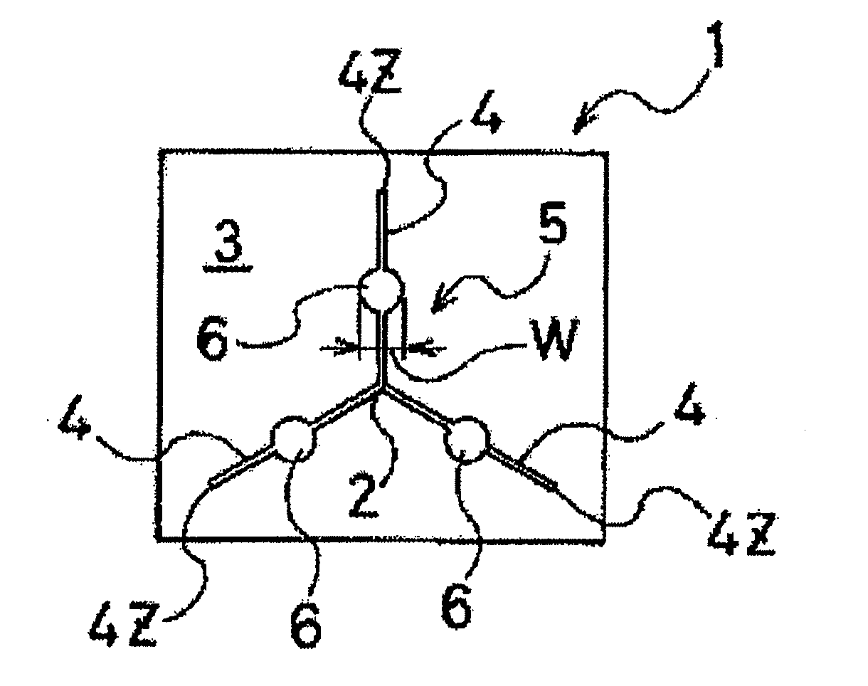
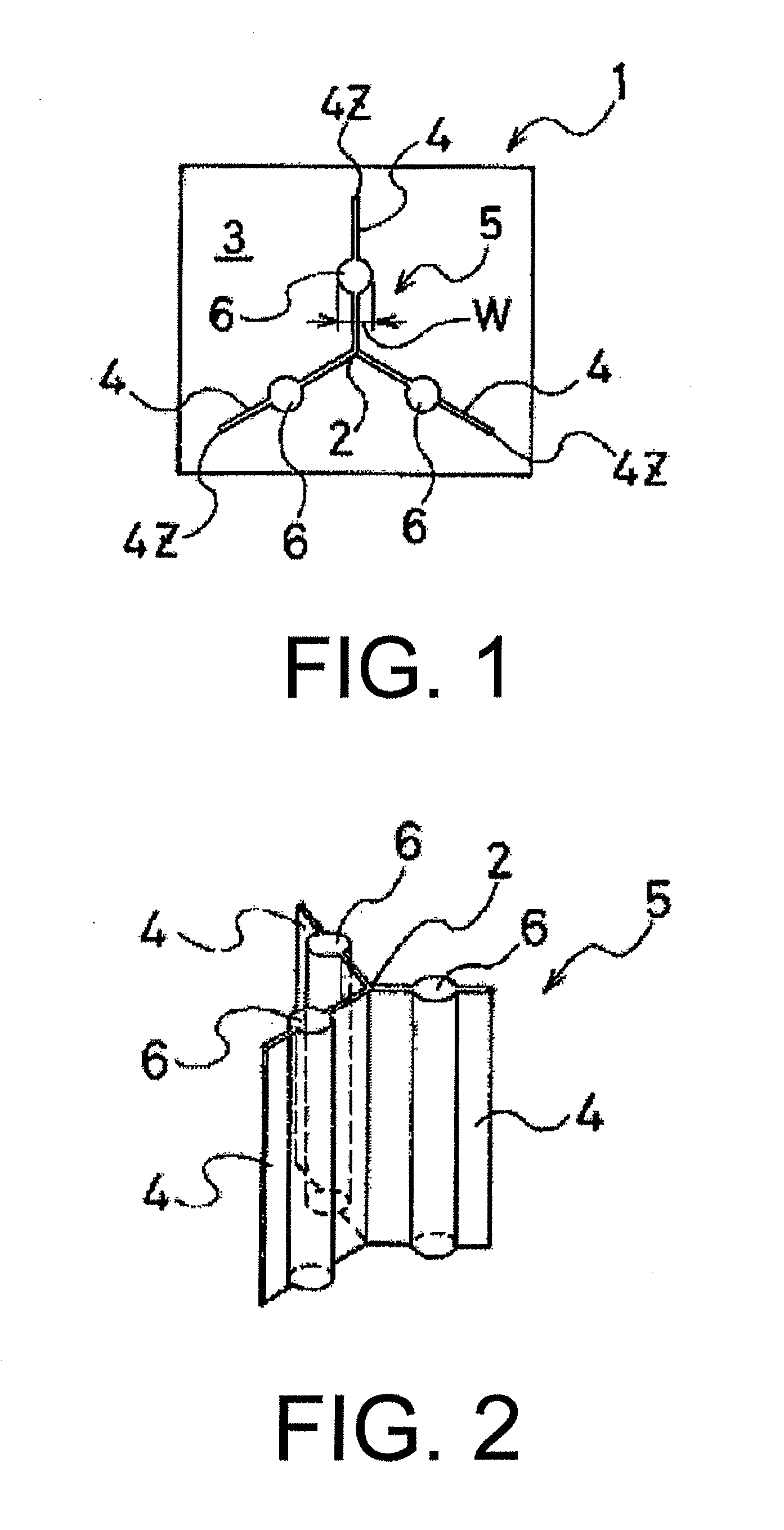
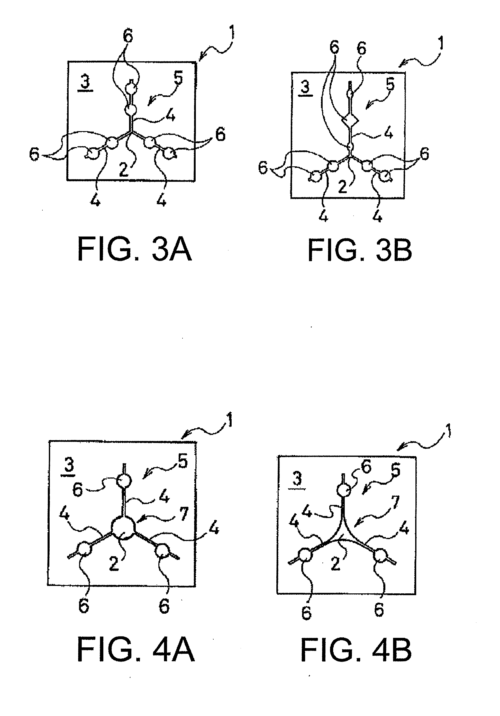
[0042]Present technology tires (Working Examples 1 to 11) and comparative tires (Comparative Examples 1 and 2) having a tire size of 195 / 65R15 91Q and the tread pattern illustrated in FIG. 7 were fabricated. The planar form of the closed sipe 5 formed in the land portion was varied as described below.

[0043]The tires of Working Examples 1 to 11 and the tires of Comparative Examples 1 and 2 were fabricated such that the planar form of the closed sipe 5, the width of the widened portion 6, a ratio of the widened portion 6 to the width of the cuts 4, whether the widened portion 6 is disposed throughout the entire length in the depth direction of the cuts, the presence / absence of the second widened portion 7, whether the second widened portion 7 is disposed throughout the entire length in the depth direction of the cuts, the presence / absence of the linear sipe 8 extending in the tire width direction, and whether the closed sipe 5 is disposed on the front edge and the back edge of the blo...


PUM


Abstract

A pneumatic tire including a closed sipe 5 in a land portion 3 formed in a tread surface 1, provided with at least three cuts 4 extending in a radiation direction from an imaginary axis 2 that extends in a depth direction of the land portion 3, and that terminate in the land portion 3. A widened portion 6 where a width of a cut is locally increased is formed at least one position of an intermediate region from the imaginary axis 2 to a terminating portion 4z of the cuts 4.

Description

TECHNICAL FIELD[0001]The present technology relates to a pneumatic tire, and particularly relates to a pneumatic tire configured so that braking performance on ice is enhanced in a tire having sipes formed in a tread surface thereof.BACKGROUND ART[0002]Sipes are commonly provided in a tread surface to enhance water absorption in order to enhance traveling performance on wet road surfaces and icy and snowy road surfaces. However, if an excessive number of sipes are disposed in the tread surface, tread rigidity will decline, leading to steering stability and braking ability being negatively affected. Therefore, conventionally, various technologies have been proposed regarding the form and arrangement of sipes (e.g. see Japanese Unexamined Patent Application No. H08-276709A).[0003]Of these proposals, Japanese Unexamined Patent Application No. H08-276709A describes obtaining high gripping force and shearing rigidity on all road surfaces by disposing multiple sipes closely to each other ...

Claims


Application Information

Patent Timeline
Patent Type & Authority Applications(United States)
IPC IPC(8): B60C11/12
CPCB60C11/11B60C11/12B60C2011/1213Y10S152/03B60C2011/1227B60C2011/1254B60C11/1281
Inventor SEKINE, KATSUYOSHIKUWAJIMA, MASATOSHI
Owner THE YOKOHAMA RUBBER CO LTD
Why Eureka
Try Eureka