Modular, prefabricated radiant panel with integrated headers

a prefabricated and radiant panel technology, applied in the field of modules and prefabricated radiant panels, can solve the problems of long installation time, complicated plants, disposal problems,

Active Publication Date: 2012-05-03
MESSANA ROBERTO
View PDF8 Cites 24 Cited by
  • Summary
  • Abstract
  • Description
  • Claims
  • Application Information

AI Technical Summary

Problems solved by technology

In the light of such remarkable advantages, in the practical use of such panel, however, some drawbacks have also been detected.
Firstly, a complex and expensive manufacturing process, especially due to the milling operation on the plasterboard required to form the coil- pipe-housing channel; as a matter of fact, this operation determines the forming of a large amount of plaster dust, the management of which remarkably complicates the plants and further creates disposal problems.
Secondly, there are long installation times, since on the sides of each panel pair a pair of supply / return pipes (headers) must be arranged, and each individual circuit of the panel must then be connected independently to such headers.
This same need determines a third drawback, i.e. that the strip of wall / ceiling taken up by the headers remains necessarily passive to the radiant exchange, reducing the useful surface which can be set aside for this function.
Lastly, with this system it is not possible to have panels wherein the front layer in sight is provided with different and additional functions (for example: fireproof, sound-absorbing, waterproof, architectural in general, etc.) different from the basic ones of mechanical support / heat conduction / external finish of the plasterboard, and this both because the milling in the rear part of the panel can imply execution problems with some types of material and, especially, because such milling locally impairs the peculiar features of the panel, which thus loses the original certification of compliance with a certain quality standard.

Method used


Image

  • Modular, prefabricated radiant panel with integrated headers
  • Modular, prefabricated radiant panel with integrated headers
  • Modular, prefabricated radiant panel with integrated headers

Examples


Embodiment Construction

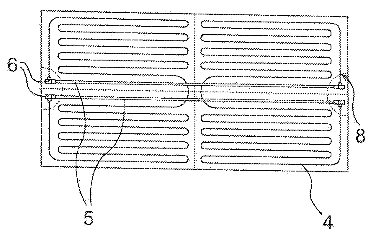
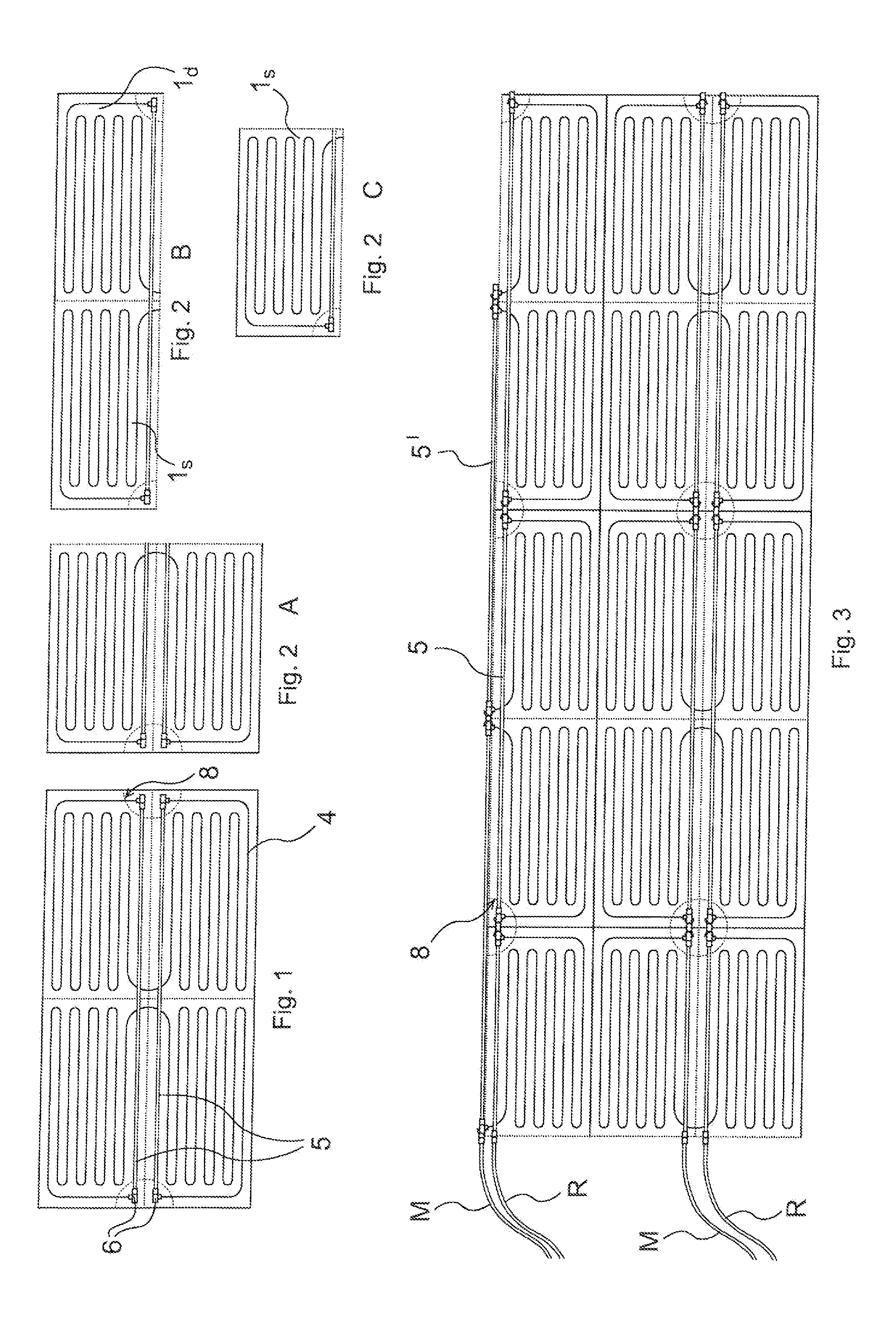
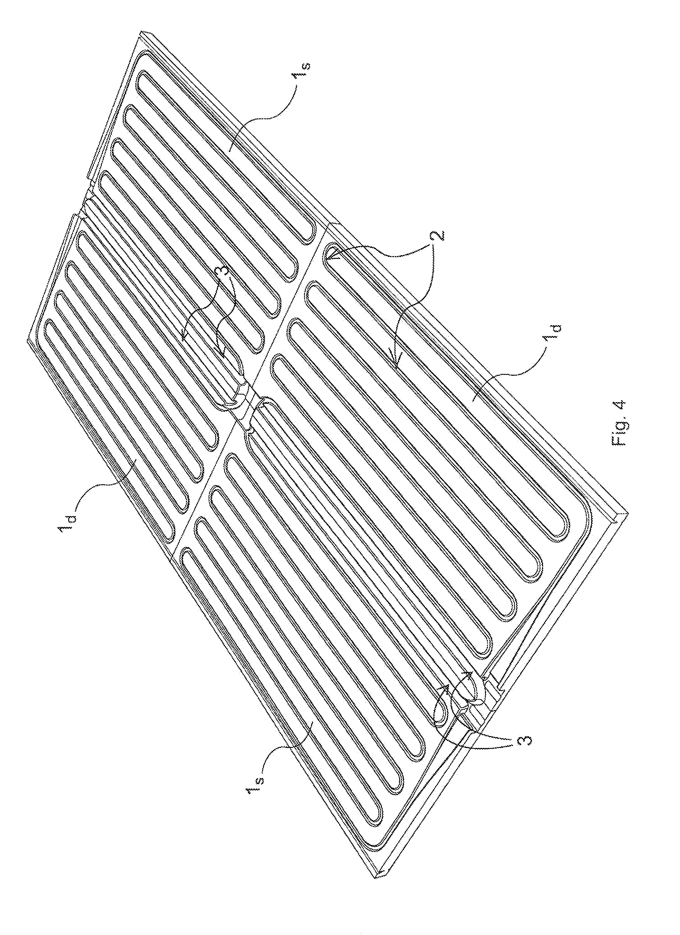
[0015]The radiant panel according to the present invention has a sandwich-like structure known per se, comprising a rear layer of thermally insulating material and a front layer provided with mechanical strength, thermal conductivity, and surface-finishing features suited to the specific application. As material for the forming of the rear layer, synthetic materials can be used, such as foamed plastic materials, such as polystyrenes or polyurethanes, or materials of a natural origin, such as cork. As material for the forming of the front layer, various types of composite layers having various functions can be used, preferably fibre-reinforced, such as for example plasterboard, fibreboard, asbestos cement, waterproof materials, sound-absorbing materials, materials of a natural origin (wood) or other similar materials. The two layers are coupled with each other by gluing and pressure, according to standard, equally widely-known procedures. For simplicity's sake, in the FIGS. 1, 2 and ...


PUM


Abstract

Modular, prefabricated radiant panel, of the type having a sandwich-like structure including a thermally insulating rear layer (1), a front layer acting as mechanical support and outer surface finish, and two radiant pipes (4) integrated in the panel for the flow of a heat-carrying fluid. The radiant pipes (4) are housed in preformed grooves (2) in the thermally insulating rear layer. In the same layer there are further provided two parallel, longitudinal grooves (3) for the housing of a pair of headers (5) which supply the radiant pipes (4). The headers (5) housed in the grooves (3) cross the entire panel and end in correspondence of the opposite short sides thereof, where they are connected to the radiant pipes (4) via T-junctions (6), a free mouth of which faces outwards for connection via sleeves (7) to T-junctions (6) of other panels, both directly and through connection pipes.

Description

FIELD OF THE INVENTION[0001]The present invention refers to a modular, prefabricated radiant panel for the conditioning of inner spaces, i.e. to a panel which is fully factory-assembled and ready for installation, designed to allow fast hydraulic connection to other similar panels and to the main pipes for the supply and return flow of the thermal carrier fluid, provided with a finished front surface and, finally, easy separable into panel submultiples. In particular the invention concerns the connection problems of the panels to the main pipes of the heat-carrying fluid which connect the panels to the central system for hot / cold water production.STATE OF THE PRIOR ART[0002]Radiant panels for room conditioning have experienced a remarkable development over the last few years and are currently one of the most interesting technical solutions to accomplish room conditioning which associates excellent performance with the opportunity of fast installation, substantially free from brickwo...

Claims


Application Information

Patent Timeline
Patent Type & Authority Applications(United States)
IPC IPC(8): F28F3/12
CPCF24D3/125F28F2210/10F24D3/142F28F9/262Y02B30/00
Inventor BUTTIGNOL, GUIDO
Owner MESSANA ROBERTO
Why Eureka
Try Eureka