Horizontal Extraction and Return Extensions in liquid storage tanks

a liquid storage tank and horizontal extraction technology, applied in the direction of fluid heaters, lighting and heating apparatus, transportation and packaging, etc., can solve the problems of no practical limitation preventing incorporation, large liquid storage tanks are usually unpressurized, and high storage volume, so as to enhance thermal stratification within the tank, reduce or eliminate flow velocity, and facilitate connection

Inactive Publication Date: 2012-05-03
LEE BRIAN ERIC +1
View PDF6 Cites 7 Cited by
  • Summary
  • Abstract
  • Description
  • Claims
  • Application Information

AI Technical Summary

Benefits of technology

[0016]When applied to various basic tank shapes, this invention provides a formed horizontal extension at the bottom of the tank. From this lower horizontal extension, a stub is directed upwardly to provide a secure and easily-maintained connection to a circulator pump. Because the stub is oriented vertically, the structural load of the pump is well transmitted to the tank with minimal stresses within the tank material.
[0017]At the top of the tank, a similar horizontal extension is used to distribute hot water returning from the array of rooftop solar collectors (or some other heating process such as a boiler). This extension acts like a baffle to reduce or eliminate the flow velocity and enhance thermal stratification within the tank. A curving lower edge to the upper horizontal extension allows return water to find the thermocline with matching temperature. This allows useful heat to be added to the storage tank without disrupting stratification even if the return water is cooler than the water at the top of the tank.
[0018]The ideal embodiment of this invention incorporates both lower and upper horizontal extensions. Used in a solar thermal system, the upper horizontal extension would include a cylindrical through passage to support a riser pipe mounted to the discharge side of the pump. This places both connections together at the top of the tank for convenient connection to the collector array, and also makes it easy to deliver tanks to the site with pumps pre-installed at the factory. With careful design of the tank, the pump can be contained entirely within the footprint of the tank.

Problems solved by technology

But rising material costs and fabrication expense result in high prices on a storage volume basis.
For these reasons and also high dry tank weights, larger liquid storage tanks are usually unpressurized.
However, there is no practical limitation preventing the incorporation of this invention into fabricated steel vessels or tanks employing a flexible liner.
For applications where a pump is used to move liquid from the tank through a circuit, the weight and vibration of the pump (usually cantilevered) result in frequent leaks at the penetration.
Such a tank may or may not be designed to take advantage of stratified thermal storage.
But typical, piping flow velocities of 1 m / sec or more cause mixing that damages stratification, and the impact is particularly damaging when there are vertical components to the return velocity.

Method used


Image

  • Horizontal Extraction and Return Extensions in liquid storage tanks
  • Horizontal Extraction and Return Extensions in liquid storage tanks
  • Horizontal Extraction and Return Extensions in liquid storage tanks

Examples


Embodiment Construction

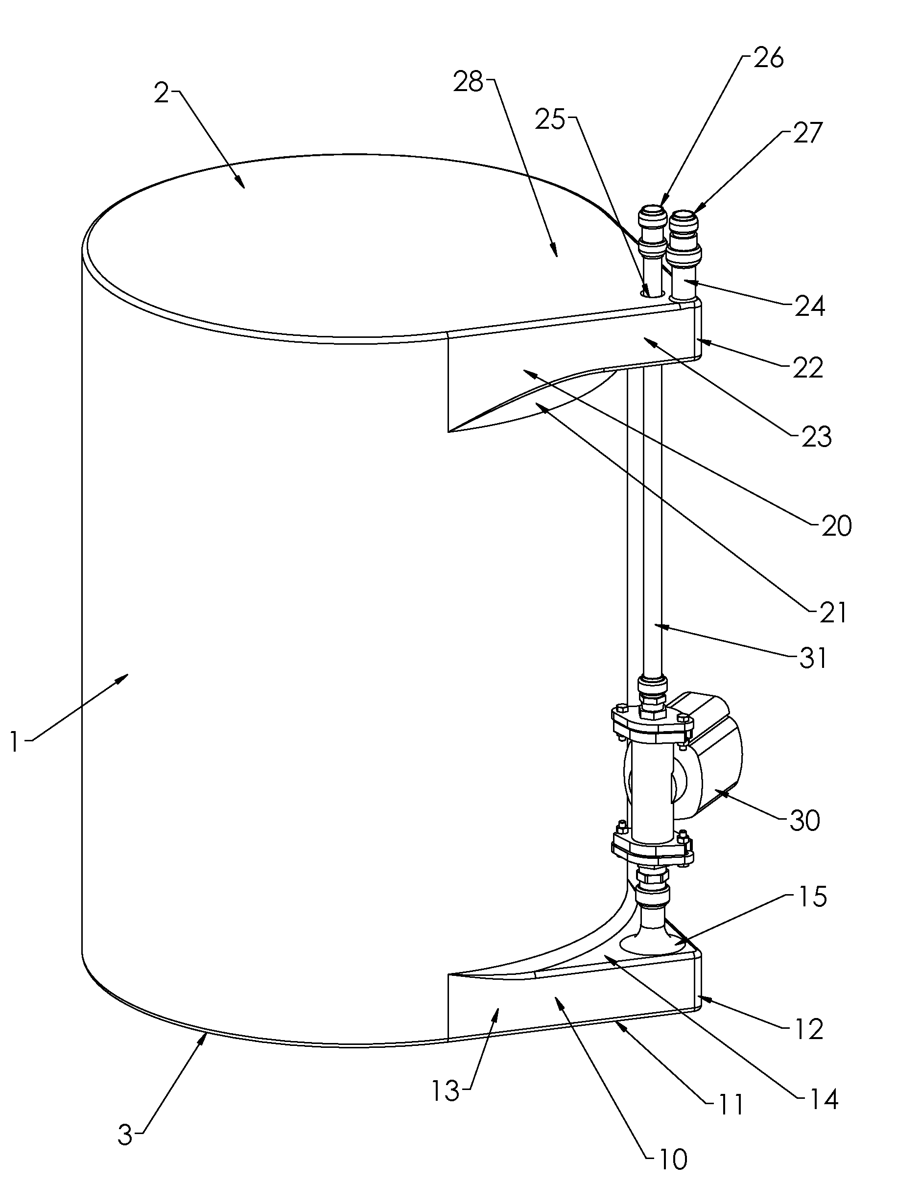
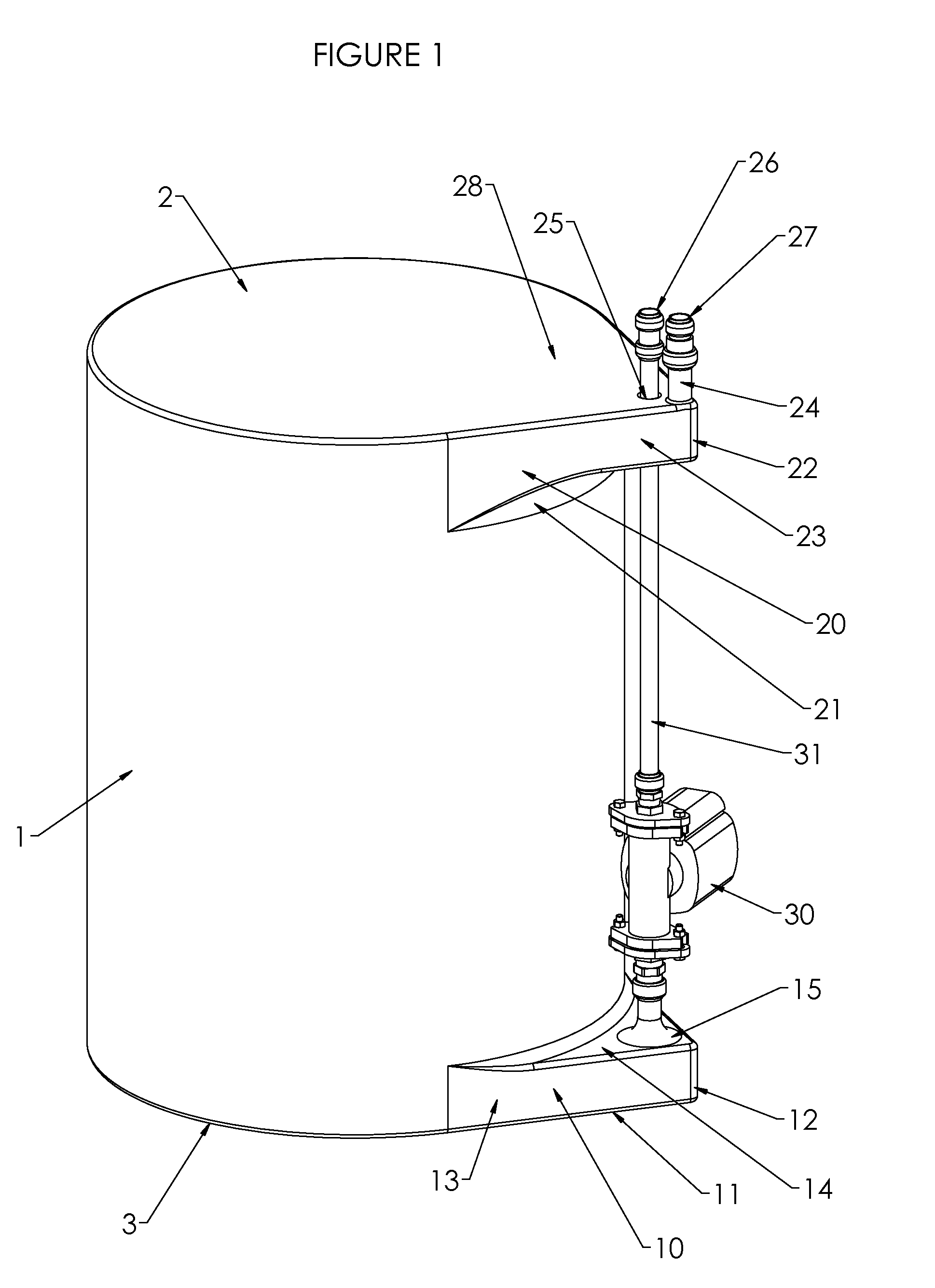
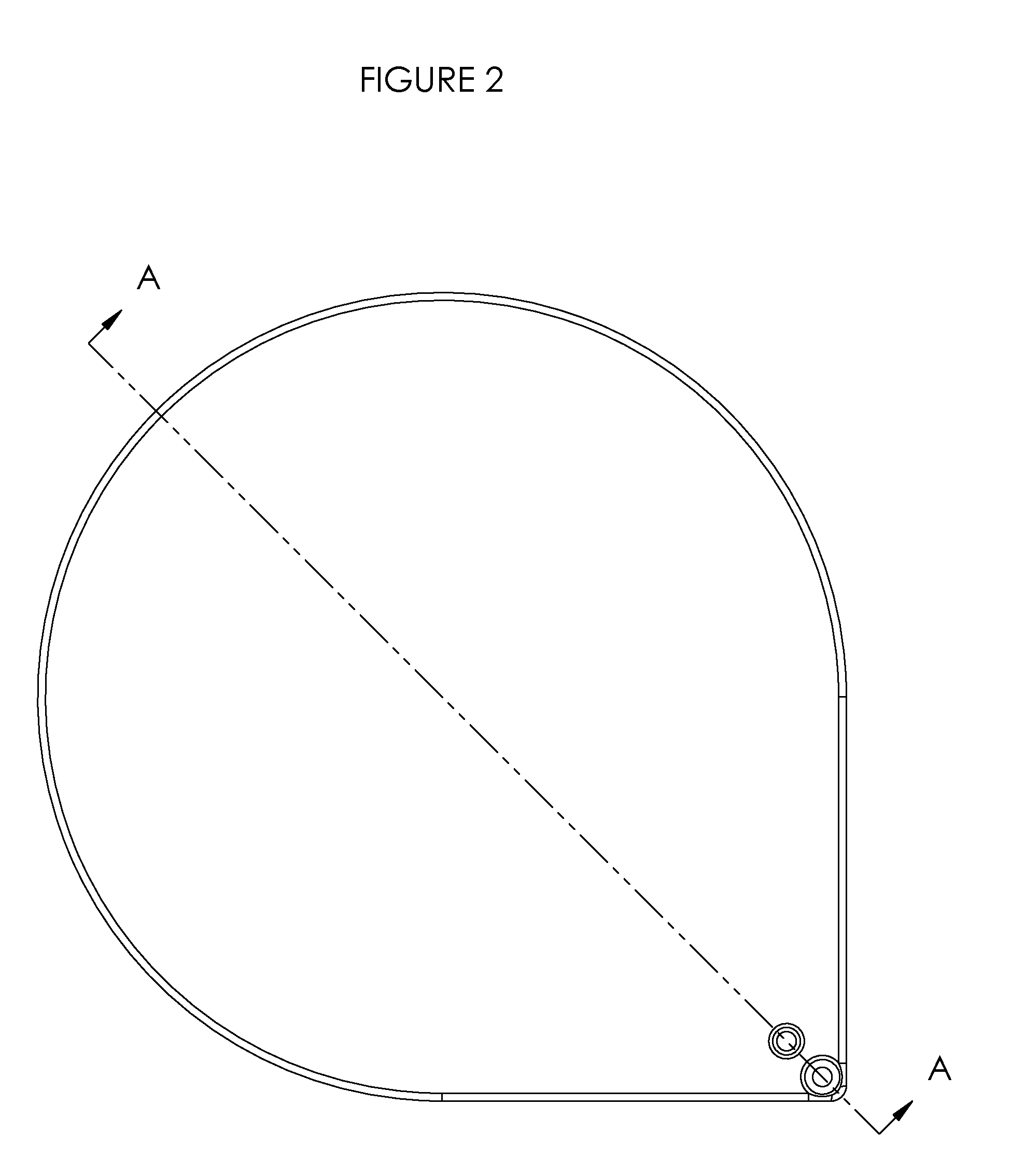
[0026]The tank 1 is a vertical-axis cylinder with planar top 2 and bottom 3; and with relatively thin, hollow bottom and top extensions 10 and 20. The bottom extension 10 has its bottom surface 11 co-planar with the tank bottom 3. The extension 10 comprises vertical surfaces 13 that extend tangentially from the circumference of the tank 1 and meet approximately at a right angle at a vertical extension corner 12. From the upper horizontal surface 14 of the bottom extension 10 extends a vertical pipe connection 15 that flares smoothly from flat to an upward vertical cylindrical shape that allows connection to the circulating pump 30. The radius of the corner 12 may vary but will normally be less than the radius of the flared pipe connection 15. This design allows the pump 30 to draw water smoothly upward with minimal pressure drop, minimal tendency to draw debris into pump 30, and with transition flow characteristics that minimize the tendency of the pump inlet flow stream to mix the ...


PUM


Abstract

This invention is an improvement to the shape of liquid storage tanks, in particular to unpressurized molded polymer tanks used for thermal storage in solar systems. All aspects of this invention are well suited to solar storage tanks, and individual aspects are suited to other liquid tank applications.
This invention provides a formed horizontal extension at the bottom of the tank. From the top of this lower extension, a hollow vertical stub provides a reliable connection to a circulator pump. Thermal performance is enhanced by ensuring the lowest and coolest water is delivered to the array of rooftop solar collectors without entraining debris from the bottom of the tank.
At the top of the tank, a similar horizontal extension is used to distribute hot water returning from the solar collectors. Flow velocity is eliminated and a curving lower edge allows return water to find the matching thermocline to avoid de-stratifying.

Description

CROSS-REFERENCE TO RELATED APPLICATIONS[0001]This application does not cross-reference existing non-provisional utility patent applications. However, it is related to USPTO provisional application 61 / 404,934.STATEMENT REGARDING STATE OF CALIFORNIA SPONSORED RESEARCH OR DEVELOPMENT[0002]This invention was made with State of California support under California Energy Commission grant number PIR-08-012. The Energy Commission has certain rights to this invention.STATEMENT REGARDING FEDERALLY SPONSORED RESEARCH OR DEVELOPMENT[0003]Not applicable.REFERENCE TO SEQUENCE LISTING, A TABLE, OR A COMPUTER PROGRAM LISTING COMPACT DISC APPENDIX[0004]Not applicable.BACKGROUND OF THE INVENTION[0005]There are three methods commonly used in the production of liquid storage tanks. Steel and stainless steel tanks are fabricated from sheet material that is cut and welded, either automated or by hand. Their resistance to elevated pressures and temperatures makes them popular for domestic water heaters an...

Claims


Application Information

Patent Timeline
Patent Type & Authority Applications(United States)
IPC IPC(8): B65D6/28
CPCF24H1/181Y02B10/20F24D2200/14F24H9/124F24H9/133
Inventor LEE, BRIAN ERICBOURNE, RICHARD CURTIS
Owner LEE BRIAN ERIC
Why Eureka
Try Eureka