Device And Method For Monitoring A Hadron Beam

a technology of hadron beam and device, which is applied in the field of hadron beam monitoring devices and methods, can solve the problems of cumbersome and time-consuming handling of these large scanning water phantoms, the device is only suitable for monitoring the geometric characteristics of the radiation beam, and the conventional radiotherapy quality assurance procedures are no longer sufficient in hadron therapy treatments

Active Publication Date: 2012-05-03
ION BEAM APPL
View PDF10 Cites 21 Cited by
  • Summary
  • Abstract
  • Description
  • Claims
  • Application Information

AI Technical Summary

Benefits of technology

[0050]Preferably, the device comprises a collimator upstream the first plate exposed to the beam. When comprised upstream the first plate exposed to th...

Problems solved by technology

Practically, conventional radiotherapy quality assurance procedures are no more sufficient in hadron therapy treatments which require, in particular, full control of beam intensity and energy.
Though the use of water phantoms is an established standard since many years, the handling of these large scanning water phantoms is cumbersome and time consuming partly because of the long water tank filling and emptying time.
Nevertheless, this device is only suitable for monitoring geometric characteristics of the radiation beam such as direction and position.
Moreover, this device is not capable of monitoring radiation characteristics during the delivery to a target.
However, this system is only suitable for controlling a divergent beam and correcting the centering and symmetry thereof.
Further, similarly to the previous one, it is not capable of monitoring radiation characteristics during the delivery to a target.
Furthermore, as the configuration of the device can change following the beam to be measured, some mechanicals stress on the frame of the chamber may modify the planarity between two electrodes causing an important deviation of the signal.
In addition, only 12 points along the axis of the beam may be measured with such a number of ionization chambers which represents a poor spatial resolution.
Such a device presents a...

Method used


Image

  • Device And Method For Monitoring A Hadron Beam
  • Device And Method For Monitoring A Hadron Beam
  • Device And Method For Monitoring A Hadron Beam

Examples


Embodiment Construction

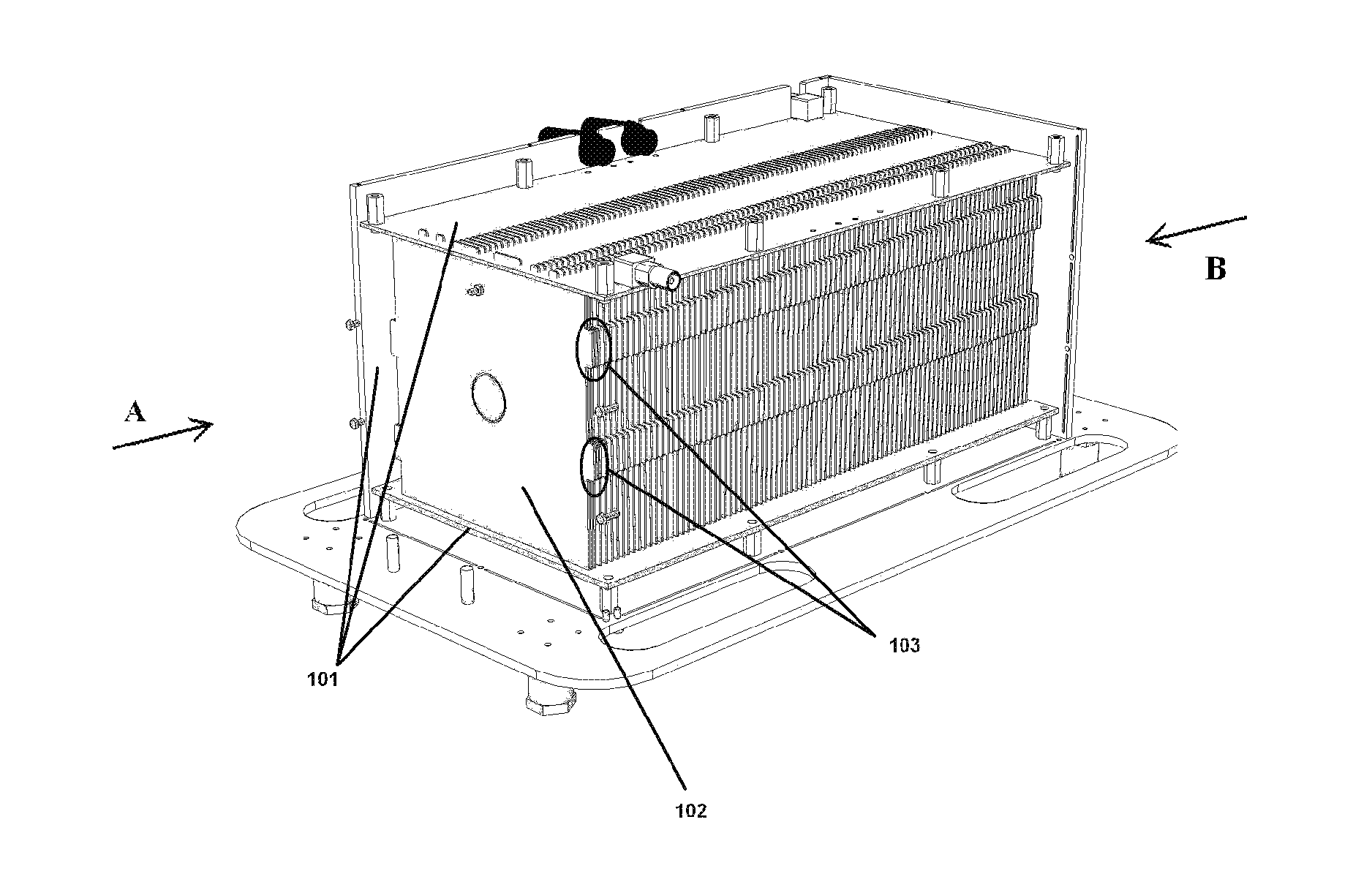
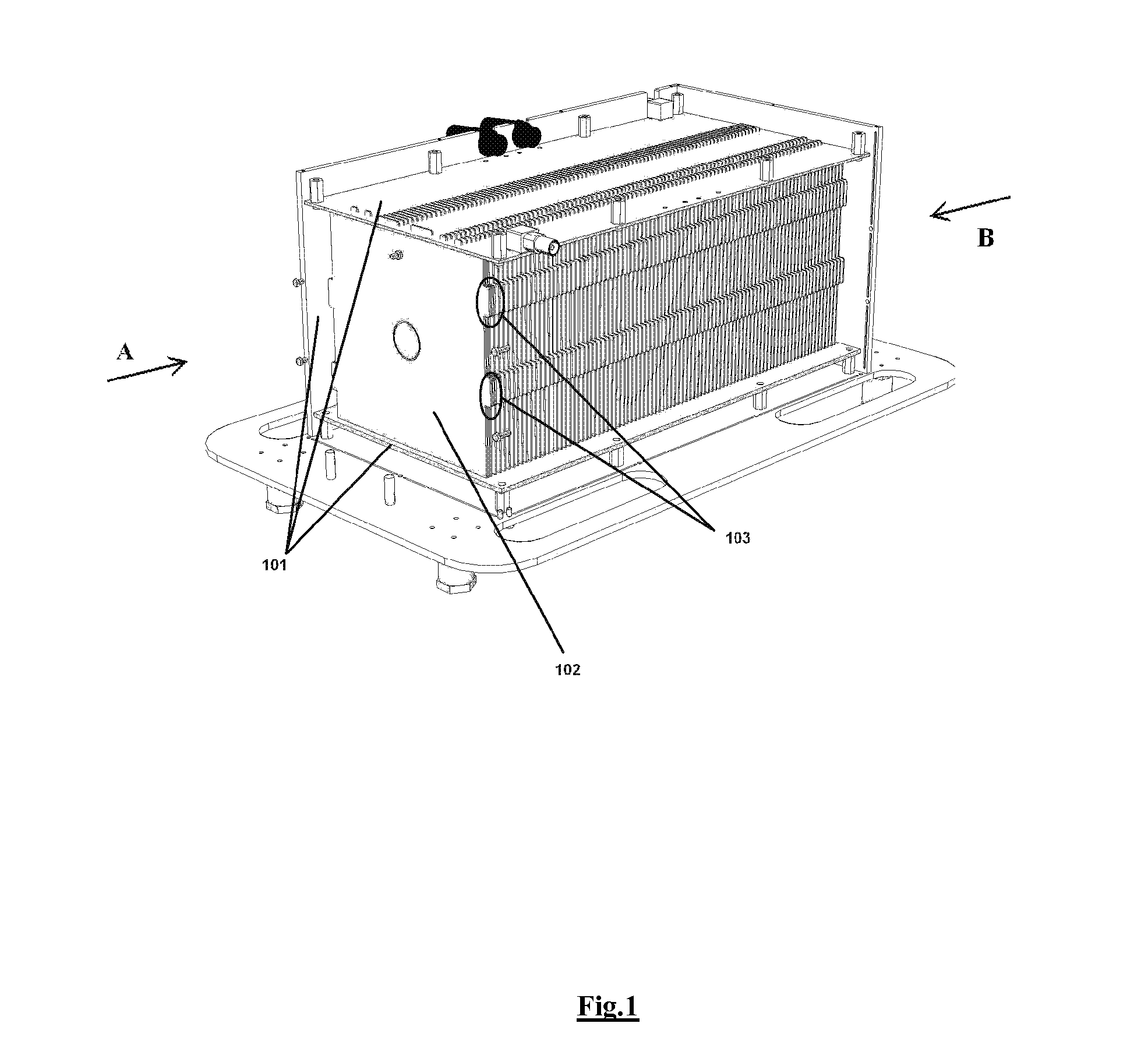
[0070]In a first aspect, the present invention relates to a device for dosimetry monitoring of a hadron beam, comprising n successive ionization chambers i obtained by a serie or stack of n+1 parallel detector plates separated from each other by a gas filled gap, each detector plates having a collecting part comprising a collecting side insulated from a bias voltage part comprising a bias voltage side and arranged in a such way that the said collecting side is facing the said bias voltage side of a subsequent detector plate or inversely, each detector plate comprising m layers of materials, the resulting assembly of these detector plates forming a plurality of ionization chamber cells, characterised in that:[0071]the thicknesses lm and the choice of the materials of each layer m constituting each detector plate as well as the gap of an ionization chamber cell i have been selected in order to satisfy the following equation for each ionization chamber i:

lgi+[∑mlm]i≈[∑mWETm]i[0072]wher...


PUM


Abstract

The present invention relates to a device for dosimetry monitoring of a hadron beam, comprising n successive ionization chambers i obtained by a serie or stack of n+1 parallel detector plates separated from each other by a gas filled gap, each detector plates having a collecting part comprising a collecting side insulated from a bias voltage part comprising a bias voltage side and ranged in a such way that the said collecting side is facing the said bias voltage side of a subsequent detector plate or inversely, each detector plate comprising m layers Lk of materials, the resulting assembly of these detector plates forming a plurality of ionization chamber cells, characterised in that: the thicknesses Ik and the choice of the materials of each layer Lk constituting each detector plate as well as the gap of an ionization chamber cell i have been selected in order to satisfy the equation (I) for each ionization chamber i, where lgi is the gas filled gap distance between two detector plates; Ik is the thickness of the corresponding layer Lk of a detector plate and; WETk is the water equivalent thickness (WET) of the corresponding layer Lk of a detector plate.

Description

TECHNICAL FIELD[0001]The present invention relates to the field of Hadron Therapy, i.e. radiation therapy using strongly interacting particles. More particularly, the invention relates to a device and a method for monitoring a hadron beam.DESCRIPTION OF RELATED ART[0002]It is well known, nowadays, that hadrons (i.e. neutrons, protons, pions, ions such as carbon ions) have physical advantages with respect to X-rays or gamma rays in the field of radiotherapy. Hadrons and in particular protons of a given energy, i.e. forming a monoenergetic beam, have a defined range and do not penetrate beyond that range. Furthermore, they deposit their maximum value of radiation energy in the so-called Bragg Peak, which corresponds to the point of greatest penetration of the radiation in a target volume being e.g. a tumour to be treated. Since the Bragg peak position depends on the energy of the hadron beam, it is evident that by precisely controlling and modifying the energy one can place the Bragg ...

Claims


Application Information

Patent Timeline
IPC IPC(8): G01T1/02
CPCG01T1/2935
Inventor MARCHAND, BRUNOBRUSASCO, CATERINADE NEUTER, SEBASTIENFRIEDL, FRIEDRICH
Owner ION BEAM APPL
Why Eureka
Try Eureka