
Torque control method for high-speed switched reluctance motor

Inactive Publication Date: 2012-05-03
KYUNGSUNG UNIV OFFICE OF IND ACAD COOPERATION
View PDF4 Cites 10 Cited by
  • Summary
  • Abstract
  • Description
  • Claims
  • Application Information

AI Technical Summary

Benefits of technology

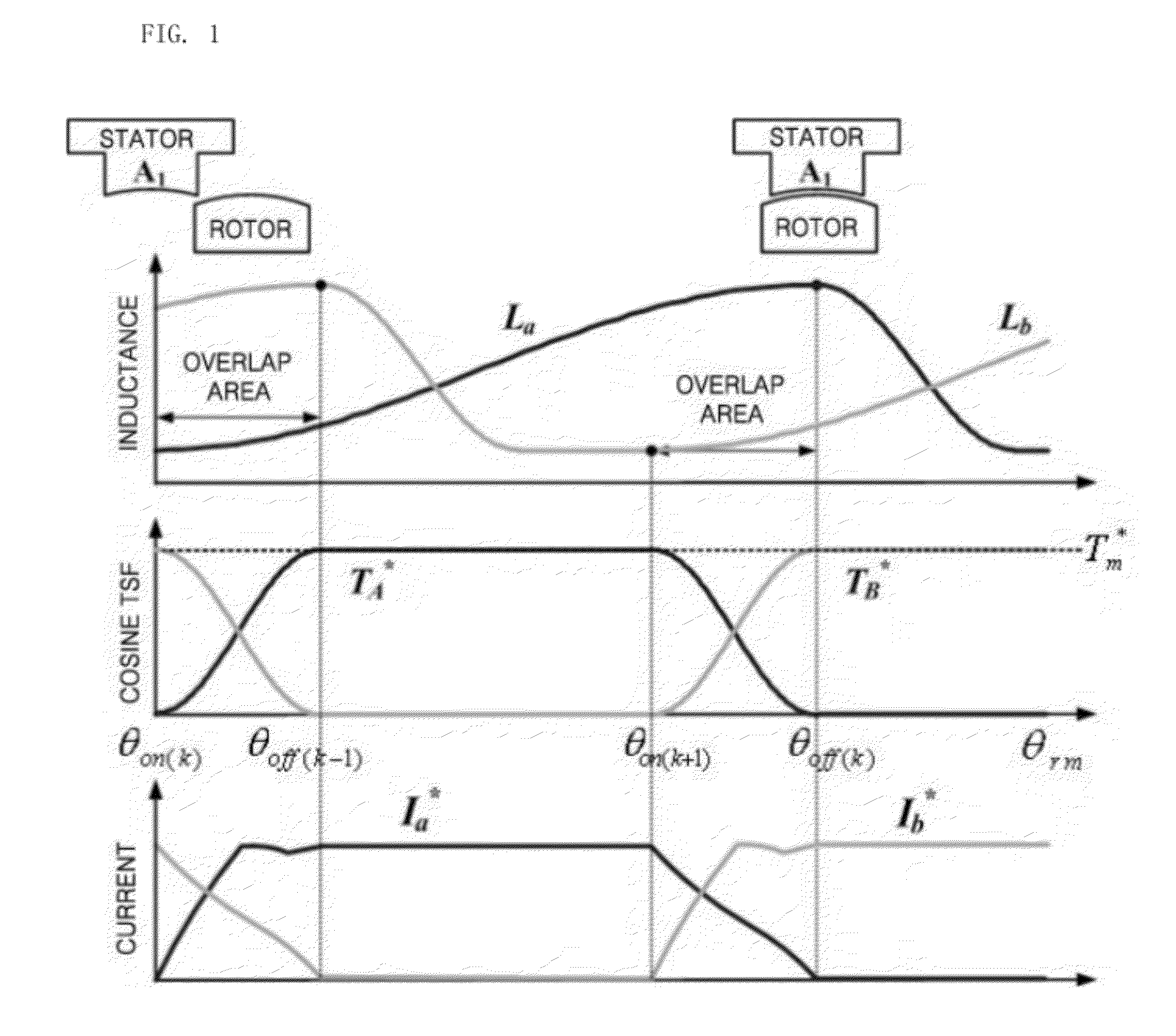
[0016]Accordingly, the present invention has been made keeping in mind the above problems occurring in the prior art, and an object of the present invention is to provide a torque control method for an SRM, which remarkably reduces a high torque ripple that occurs in an overlap area in which a phase switches from an active phase to a subsequent excited phase, in consideration of the non-linear characteristics of an SRM, thus improving drive efficiency even in the high-speed operation interval of the SRM.

Problems solved by technology

However, the greatest disadvantage of the high-speed SRM is that a torque ripple is greater than that of other motors.
The above conventional technology is advantageous in that relatively smooth torque output can be derived using basic control principles, but has limitations in that complicated switching rules are required to generate a smooth torque in an overlap area, and control performance is determined based on the switching rules determined in this way.
Further, there is another problem in that when a DITC technique is used, an additional current controller must be employed.
However, the conventional technology is still problematic in that a torque ripple in an overlap area is not especially taken into consideration, and thus the influence of the torque ripple that occurs due to tail current in the overlap area cannot be excluded.
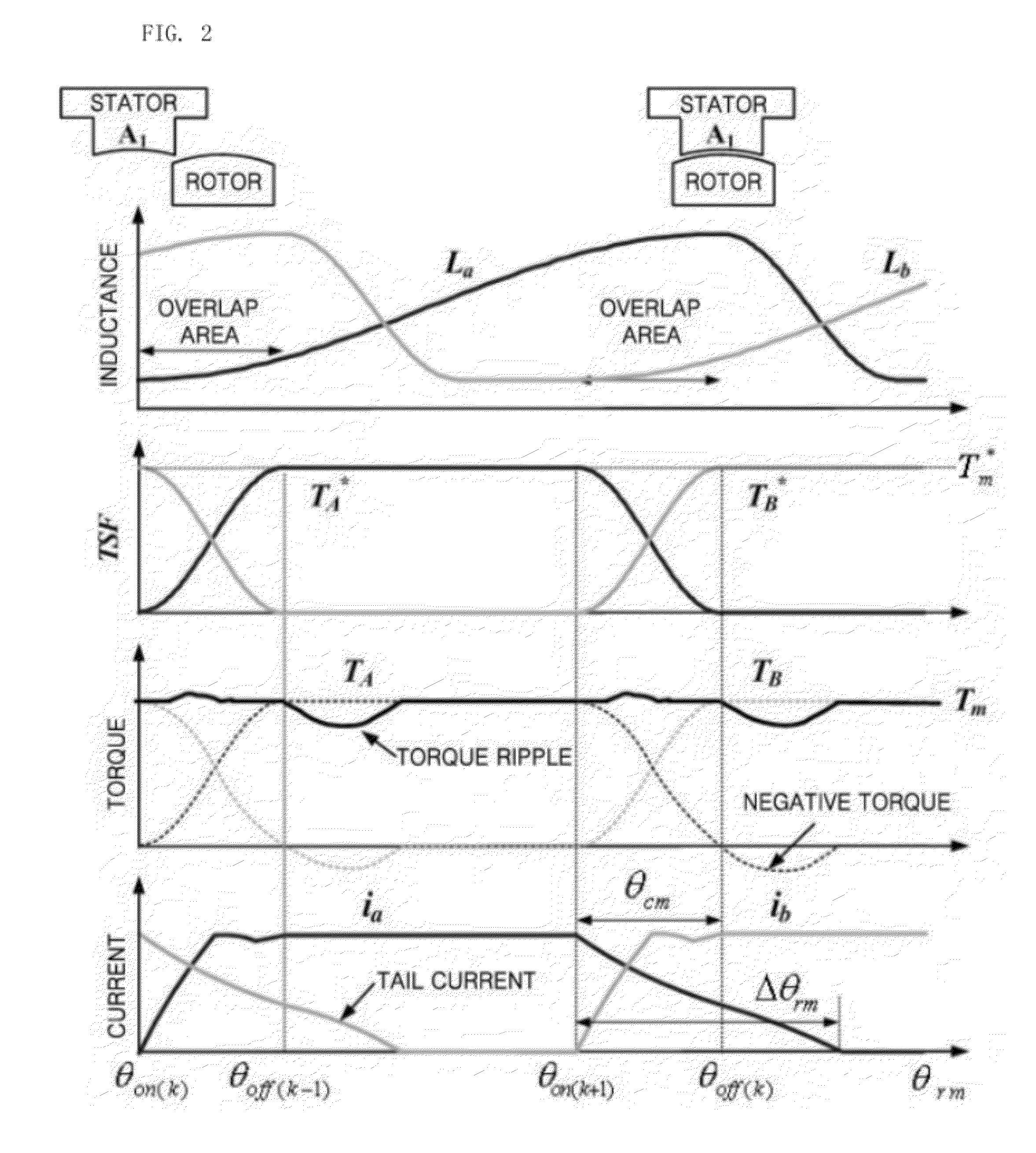
However, since a torque overlap interval is very short, the current cannot be completely extinguished during the interval, and then tail current is generated.
Because this tail current exists in the falling section of inductance, a negative torque is generated, and a high torque ripple occurs for the entire torque due to the negative torque.
That is, the torque control method for the SRM using the existing torque sharing function is simple, but is problematic in that the torque ripple cannot be mitigated at the start and end portions of the overlap area in high-speed operation mode.

Method used


Image

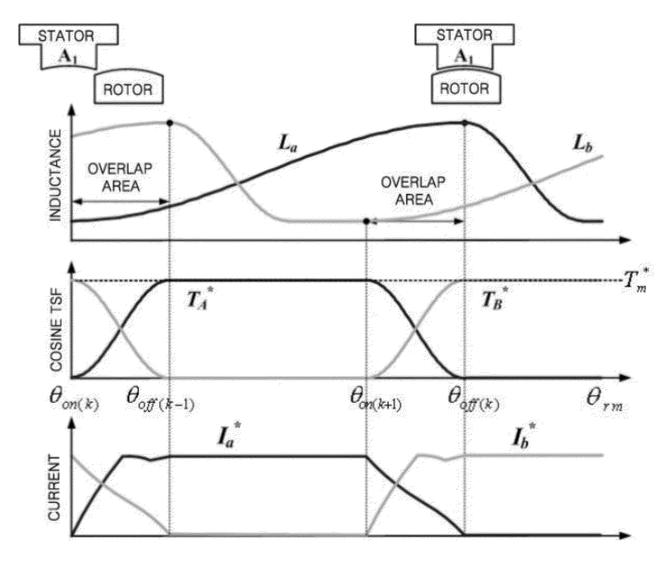
  • Torque control method for high-speed switched reluctance motor
  • Torque control method for high-speed switched reluctance motor
  • Torque control method for high-speed switched reluctance motor

Examples


Embodiment Construction

[0029]Hereinafter, embodiments of the present invention will be described in detail with reference to the attached drawings. Further, in the description of the present invention, if detailed descriptions of related well-known technologies or constructions are determined to make the gist of the present invention unclear, the detailed descriptions will be omitted.

[0030]Further, the terms used in the present specification are defined in consideration of the functions in the present invention, and may vary according to the intention or usage of a user or an operator, so that the terms should be defined based on the entire contents of the present specification describing the present invention.

[0031]FIGS. 3A to 3D are waveform diagrams showing a torque control method according to an embodiment of the present invention, FIG. 4 is a control block diagram showing a torque sharing function required to implement a torque control method according to an embodiment of the present invention, FIG. ...


PUM


Abstract

Disclosed herein is a torque control method for a high-speed Switched Reluctance Motor (SRM), which controls a torque in the high-speed operation of a 2-phase SRM. In the torque control method for a high-speed SRM, a positive torque (T*mA) of an active phase (A phase) of the two phases of the SRM is compensated for based on a negative torque attributable to an inactive phase (B phase) of two phases during a compensation control enable interval (ENA) ranging from a time point at which the active phase (A phase) is turned on to a time point at which tail current of the inactive phase (B phase) remains. Accordingly, the present invention can remarkably reduce a torque ripple occurring in high-speed operation mode in consideration of the influence of a negative torque attributable to tail current.

Description

BACKGROUND OF THE INVENTION[0001]1. Field of the Invention[0002]The present invention relates, in general, to a torque control method for a high-speed Switched Reluctance Motor (SRM), and, more particularly, to a torque control method for a high-speed SRM, which compensates for the positive torque of an active phase (A phase) of two phases based on a negative torque attributable to an inactive phase (B phase) during a compensation control enable interval (ENA) ranging from a time point at which the active phase (A phase) is turned on to a time point at which the tail current of the inactive phase (B phase) remains, in order to remarkably reduce a high torque ripple that occurs in an overlap area in which the phase switches from an active phase to a subsequent excited phase, in consideration of the non-linear characteristics of a high-speed SRM, and thus to improve drive efficiency.[0003]2. Description of the Related Art[0004]Typically, a Switched Reluctance Motor (SRM) is a kind of ...

Claims


Application Information

Patent Timeline
IPC IPC(8): H02P6/08
CPCH02P23/0086H02P25/098Y02P80/116Y02P80/10H02P2209/09Y10S388/912
Inventor AHN, JIN-WOOLEE, DONG-HEE
Owner KYUNGSUNG UNIV OFFICE OF IND ACAD COOPERATION
Learn More