Measuring device for noncontact measurement of distances to a target object

a non-contact, measuring device technology, applied in the direction of distance measurement, instruments, surveying and navigation, etc., can solve the problems of inability to manage, system complexity is too large for applications on construction sites or in construction and renovation jobs, and software-based approaches have proved inadequate in compact measuring devices, in particular handheld ones, to achieve the effect of simplifying processing operations, easy visualization, and convenient handling

Inactive Publication Date: 2012-05-03
HILTI AG
View PDF12 Cites 39 Cited by
  • Summary
  • Abstract
  • Description
  • Claims
  • Application Information

AI Technical Summary

Benefits of technology

[0015]It is an object of the present invention to provide a measuring device and a method of the type defined in the introduction with the aid of which distances to a target object are determinable in a comparatively efficient manner which is simple in particular. Lateral distances on a surface of the target object such as, for example, lateral distances on a plane of the target object are to be determinable in particular. It should be possible in particular to indicate the lateral distances on the target object at least approximately. In particular the base should be created for enabling a documentation and attribution of measured distances, i.e., in particular lateral distances on the target object, in a manner that is easily visualized with an easily handled measuring device, in particular in the form of a handheld device. In particular it should additionally be possible to indicate distances between the measuring device and the target object.
[0016]The present invention is based on the consideration that a control and computation unit, having a memory and taking into account the available computation and storage capacities, may also be configured for handheld measuring devices in such a way that it is possible to provide at least approximate information about lateral distances on the target object by using the results of a distance measuring unit and a photoelectric image acquisition unit. The present invention is also based on the consideration that a simplification of a processing operation in the control and computation unit according to the proposed concept is advantageous. For this purpose, the present invention initially provides an image processing unit which is designed to define at least a number of the target points on the target object as a number of corresponding pixels in at least one photoelectric image. The number of points in the present case is understood to be an integer of one, two, three, four, etc., or more points. The measuring point may but need not necessarily be part of the image. A measuring point is advantageously part of the image. In particular a measuring point may be one of the target points. This is not normally the case but it may prove to be advantageous. In other words, the concept of the present invention is based on the analysis of initially exactly one photoelectric image and the single measuring point recorded with the photoelectric image. In particular the concept of the present invention may already be implemented advantageously on the basis of a single photoelectric image obtained with a single [photographic] shot. In particular it is sufficient for implementing the concept that the photoelectric image acquisition unit has a single search lens and camera lens. However, the present invention is not limited thereto. Likewise there is a significant advantage of the concept in its comparatively simple implementability.
[0017]The present invention has recognized that the distance measuring device supplies a distance between a reference point and the measuring point on a target object simultaneously or in real time to the recording of the photoelectric image. Accordingly, the present invention additionally provides that the control and computation unit is designed to assign the pixel, which is defined and corresponds to a target point, to the distance of the reference point to the measuring point. An allocation formed in this way between the distance supplied by the distance measuring unit and the measuring point on the one hand and a pixel defined in the image of the photoelectric image acquisition unit on the other hand has proven to be a sufficient basis for approximately determining lateral distances on the target object in particular.
[0019]Within the scope of a particularly advantageous refinement of the present invention, it is provided that exactly one single photoelectric image results from a single recording of the target object. In particular it is provided for this purpose that precisely one measuring point is allocated to the photoelectric image. The measuring point is advantageously allocated to one of the number of pixels in the single photoelectric image but not to one of those pixels allocated to one target point. Such a recording of a photoelectric image with a measuring point and an additional distance measurement to the measuring point may be accomplished using a single viewfinder lens and camera lens, which greatly simplifies the design of the measuring device.

Problems solved by technology

Such systems may be too complex for applications at construction sites or in construction and renovation jobs and are susceptible to problems and are thus ultimately not manageable.
Such software-based approaches have proven to be inadequate in compact measuring devices, in particular those which are handheld.

Method used


Image

  • Measuring device for noncontact measurement of distances to a target object
  • Measuring device for noncontact measurement of distances to a target object
  • Measuring device for noncontact measurement of distances to a target object

Examples


Embodiment Construction

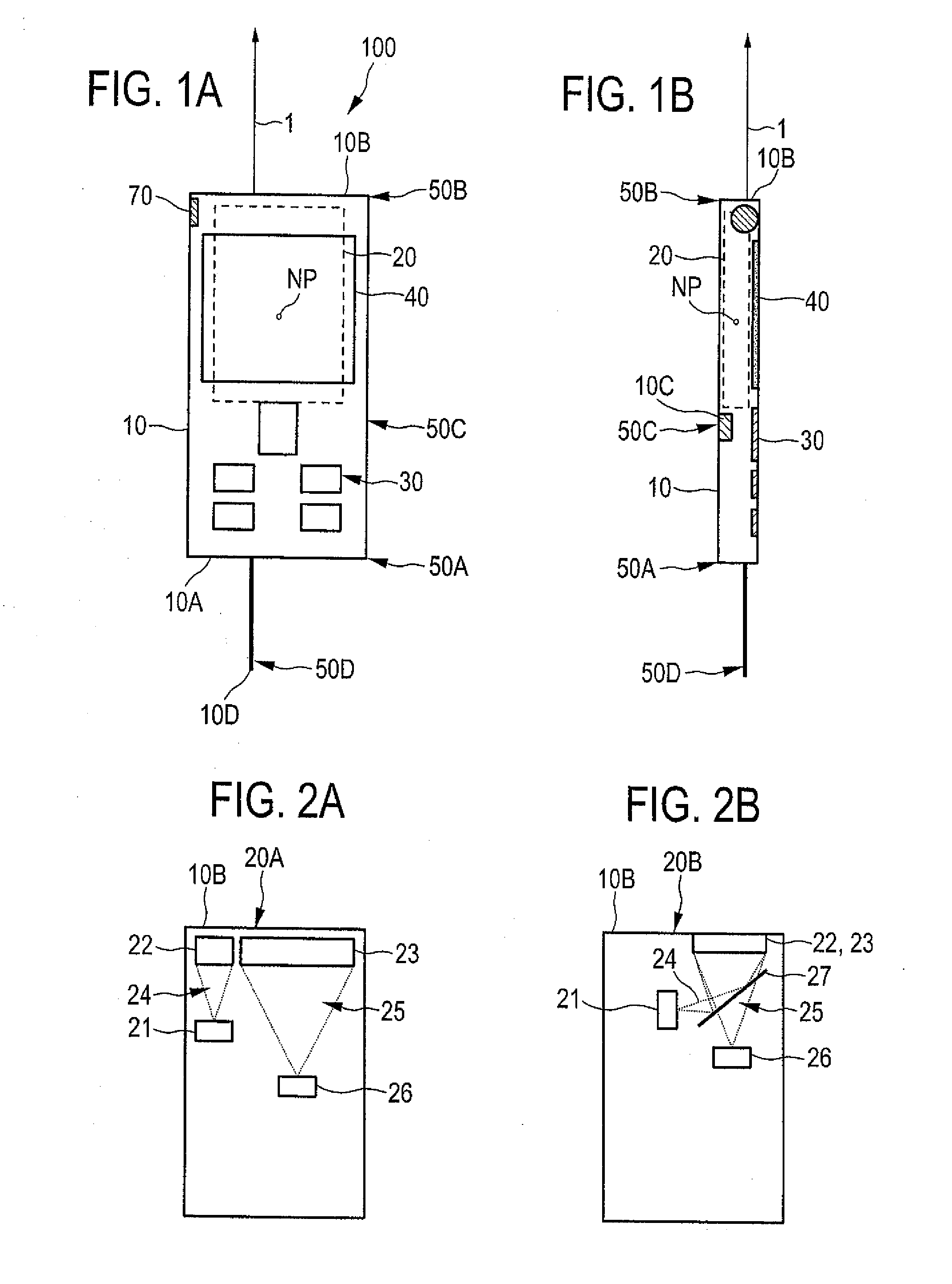
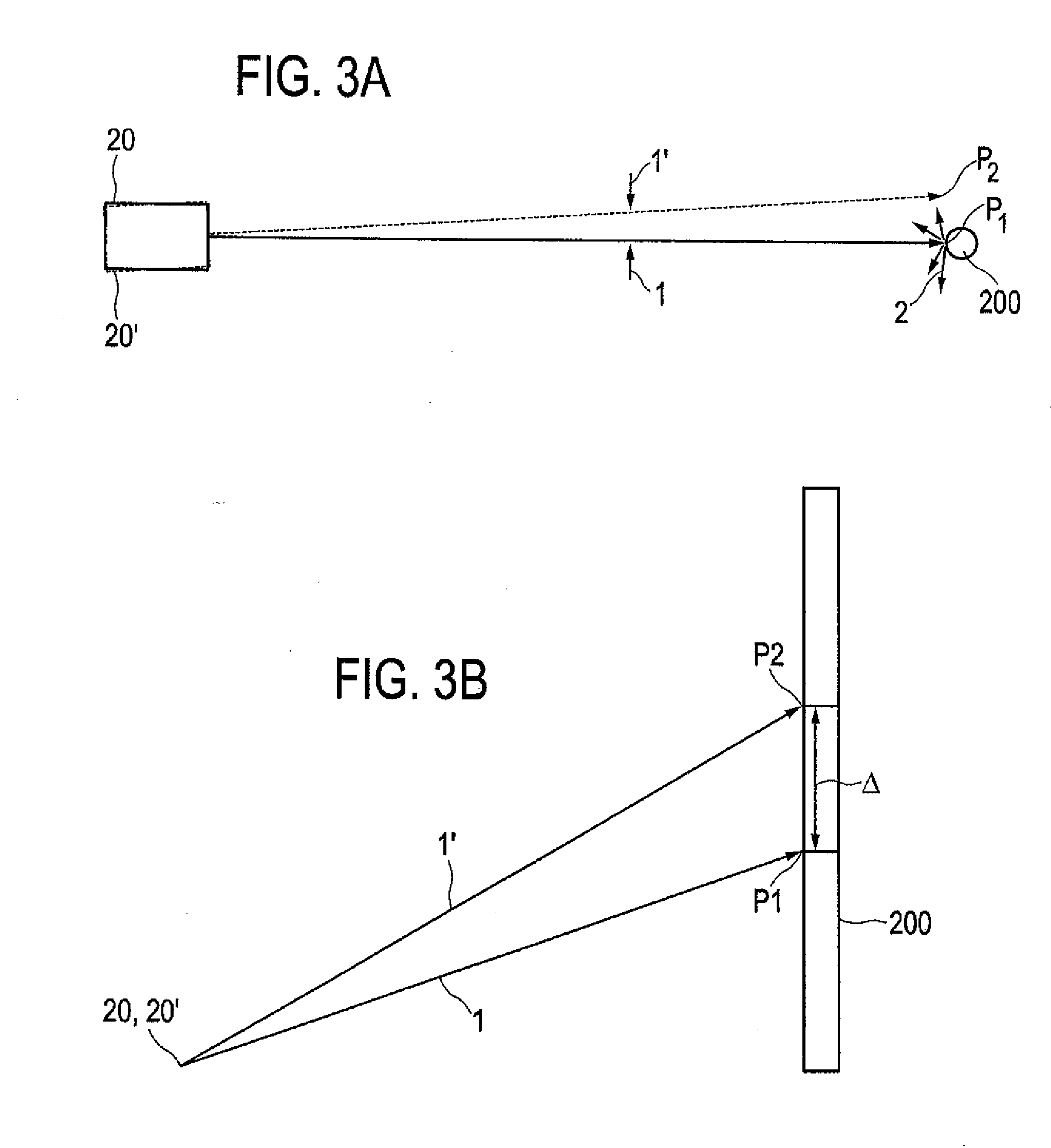
[0049]FIGS. 1A and 1B show a measuring device 100 in the form of a handheld device for a noncontact measurement of a distance z, which is defined more precisely in FIG. 5, to a target object 200 shown as an example in FIGS. 3A and 3B. Measuring device 100 is shown in a top view of an operator side of housing 10 in FIG. 1A and in a side view of housing 10 in FIG. 1B—the components of measuring device 100 are represented schematically.

[0050]Housing 10 of measuring device 100 which is designed in the form of a laser distance measuring device for example, is designed for manual use—so in the present case, it is not insignificantly larger than the area of a hand with corresponding haptics, possibly also ergonomics. Likewise, housing 10 is shown as a rectangle for the sake of simplicity. Housing 10 accommodates distance measuring unit 20 in the form of a laser distance measuring unit utilizing optical measuring beam 1. Possible variants of distance measuring unit 20 are shown in FIGS. 2A ...


PUM


Abstract

A measuring device, having: a housing; a distance measuring unit situated in the housing uses an optical measuring beam, with the aid of which the distance between a reference point and at least one measuring point on a target object is measurable without contact; a photoelectric image acquisition unit situated in the housing having a viewfinder and camera lens situated in the housing as well as an image path connecting them for detecting target points of the target object, an image processing unit and a control and computation unit with the aid of which the image of the image processing unit is displayable. The image processing unit defines target points pixels in exactly one single photoelectric image, the control and computation unit allocating the distance of the reference point to the measuring point to at least one of the pixels, the allocation available for further processing.

Description

[0001]This claims the benefit of German Patent Application DE 10 2010 043136.2, filed Oct. 29, 2010 and hereby incorporated by reference herein.[0002]The present invention relates to a measuring device, in particular in the form of a handheld device, for a noncontact measurement of a distance to a target object. The present invention also relates to a method for noncontact measurement of distances on a target object.BACKGROUND[0003]A measuring device may be used as a handheld distance meter using a suitably designed laser measuring unit, for example.[0004]A noncontact measurement of a distance to a target object is usually made with the aid of an optical measuring beam, for example, a laser beam. Regardless of the measuring beam used, fundamentally different methods are known for distance measuring; for example, a distance to a target object may be determined in a noncontact method with the aid of a travel time measurement, a phase measurement or laser triangulation. For implementin...

Claims


Application Information

Patent Timeline
Patent Type & Authority Applications(United States)
IPC IPC(8): G01C3/04G01S17/86
CPCG01C15/002G01S17/023G01S17/08G01S17/86
Inventor GOGOLLA, TORSTENTIEFENTHALER, STEFANHABENBACHER, HERWIGWURSCH, CHRISTOPHSCHMIDT, PEERDOYEN, JEAN-PHILLIPPE
Owner HILTI AG
Why Eureka
Try Eureka