Optical multiplexing terminating device, passive optical network system and method for allocating wavelength

a technology of passive optical network and terminating device, which is applied in multiplex communication, electrical equipment, electromagnetic network arrangement, etc., can solve the problems of optical signals outputted from the onus colliding and interfering with the trunk optical fiber, and achieve the effect of reducing the amount of power consumption

Inactive Publication Date: 2012-05-03
HITACHI LTD
View PDF2 Cites 30 Cited by
  • Summary
  • Abstract
  • Description
  • Claims
  • Application Information

AI Technical Summary

Benefits of technology

[0059]With the invention, it is possible to provide the optical multiplexing terminating device, the passive optical network system and the method for allocating wavelength that a waste of power consumption can be reduced as much as possible, based on the end user traffic.

Problems solved by technology

That is, since the length of optical fiber (transmission distance) including the trunk optical fiber and the branch optical fiber from the OLT to each ONU varies, the transmission delay (delay amount) between each ONU and the OLT varies, whereby even if each ONU transmits the signal at different timing, there is possibility that the optical signals outputted from the ONUs may collide and interfere on the trunk optical fiber.

Method used


Image

  • Optical multiplexing terminating device, passive optical network system and method for allocating wavelength
  • Optical multiplexing terminating device, passive optical network system and method for allocating wavelength
  • Optical multiplexing terminating device, passive optical network system and method for allocating wavelength

Examples


Embodiment Construction

[0079]The configuration and operation of a PON according to this embodiment and a method for allocating wavelength for implementing this means will be described below in detail using the drawings.

[0080]1. Passive Optical Network System

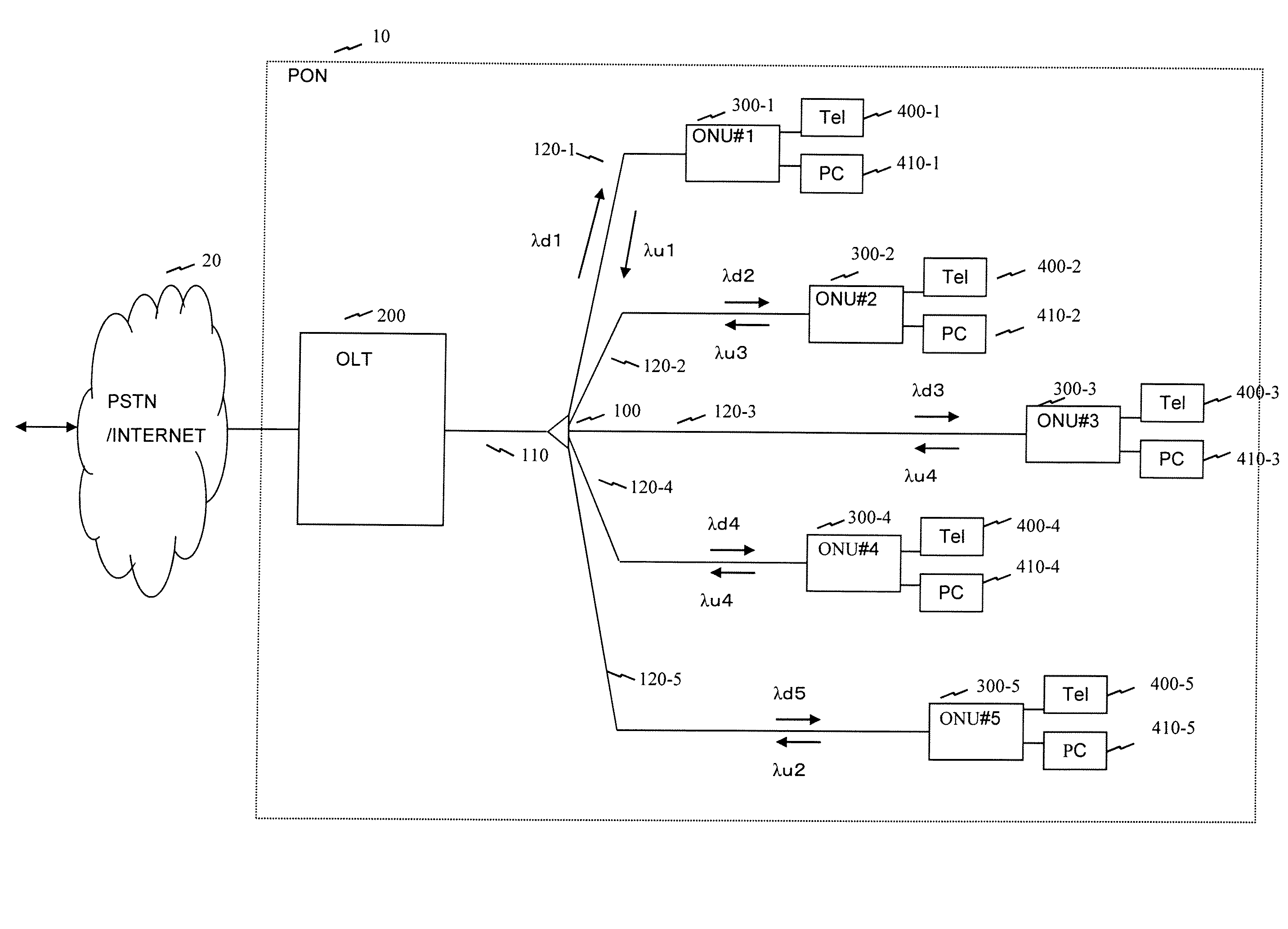
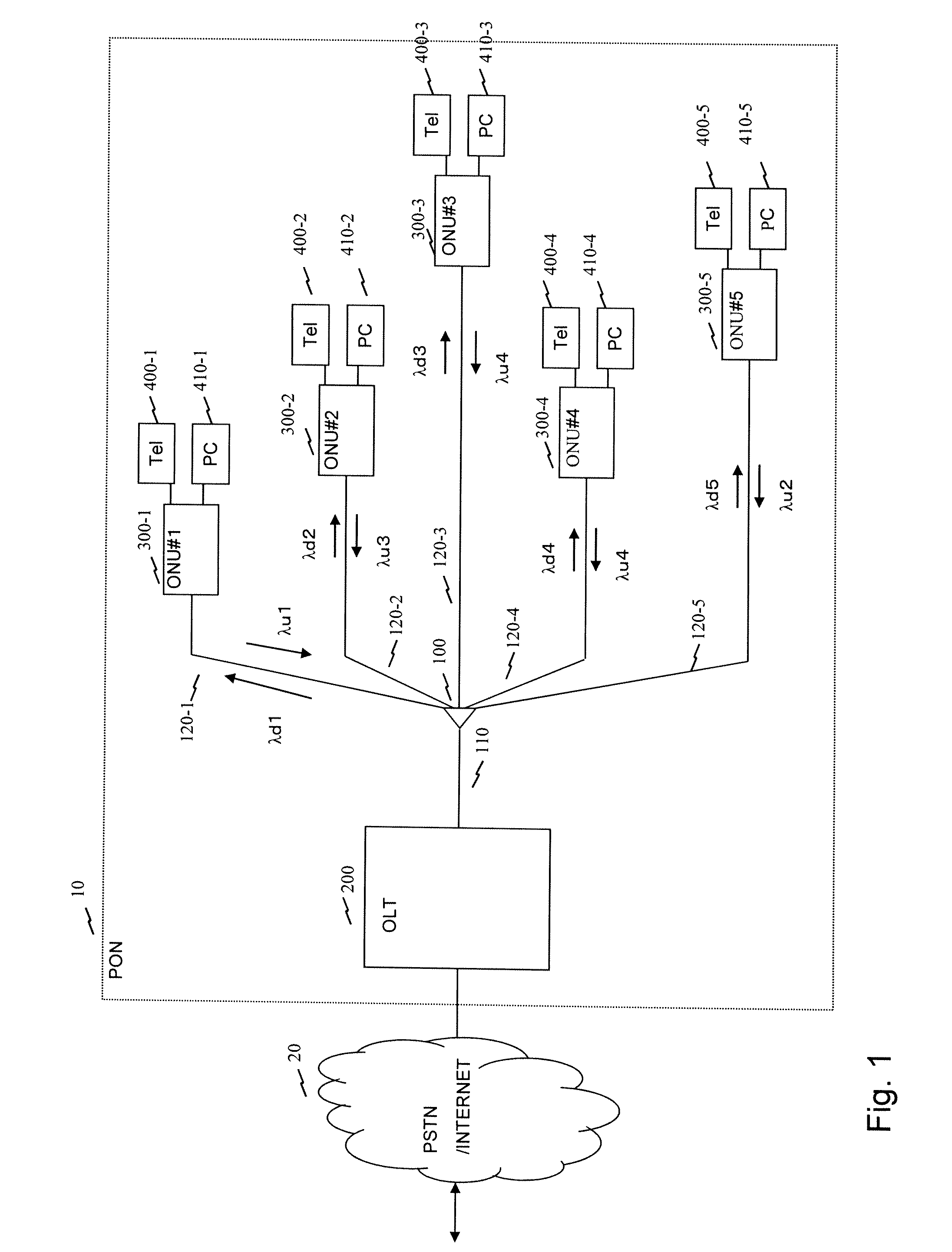
[0081]In the following explanation, an PON configured to make the wavelength division multiplexing of data by allocating wavelength to each of five ONUs connected to an OLT is supposed, in which the wavelength allocated to downlink data from the OLT to each ONU is one of allocating statically a unique wavelength (λd1, λd2, . . . , λd5) to each of the ONUs, and the wavelength allocated to uplink data from the ONU to the OLT is one of dynamically allocating the wavelengths (λu1, λu2, λu3, λu4) capable of transmitting data of 100 Mbit / s (correctly 103.68 Mbit / s and the length of time slot is 1620 bytes), 500 Mbit / s (correctly 518.4 Mbit / s and the length of time slot is 8100 bytes), 1 Gbit / s (correctly 1036.8 Mbit / s and the length of time slot is 16200 byt...


PUM


Abstract

A passive optical network system such that the power consumption can be reduced as much as possible according to the end-user traffic. An OLT uses the DBA function thereof and sequentially uses frequencies in ascending order of transmission rate in order to sequentially allocate bands to ONUs in ascending order of the requested bandwidth. At this time, a frequency to be allocated is selected so that the bandwidth allocated to each ONU is narrower than a maximum bandwidth through which transmission using the allocated wavelength is enabled. An OLT uses a grant area to specify the transmission timing of the secondary station and to inform the specified transmission timing to the secondary station. In addition, an area is set for storing information used to inform the secondary station of a new frequency to be used.

Description

TECHNICAL FIELD[0001]The present invention relates to an optical multiplexing terminating device, a passive optical network system and a method for allocating wavelength, and more particularly to an optical multiplexing terminating device in a passive optical network system in which plural optical network terminating devices such as subscriber connecting devices share an optical transmission line, the passive optical network system and a method for allocating wavelengthBACKGROUND ART[0002]To transmit and receive a large volume of image signal or data via a communication network, the higher speed and wider bandwidth of the communication network have been carried out in an access network for connecting the subscriber to the communication network, whereby a Passive Optical Network system (hereinafter referred to as a PON) has been introduced as defined in the recommendation G.987.1-3 of the International Telecommunication Union (hereinafter referred to as ITU-T). The PON is a system in...

Claims


Application Information

Patent Timeline
Patent Type & Authority Applications(United States)
IPC IPC(8): H04J14/00H04B10/27H04B10/272
CPCH04J14/0282H04J14/0246H04J14/0252H04Q2213/1301
Inventor SAKAMOTO, NORIHIROKAZAWA, TOHRUYAJIMA, YUSUKETSUCHIYA, AKIHIKO
Owner HITACHI LTD
Why Eureka
Try Eureka