Vertical Filtering and Separating Suction Machine of Chips, Steam and Smoke by Change of Air Direction, for Machining Center, Lathe Machine or Other Machines Generating Steam from Oil or Coolant

a filtering machine and vertical filtering technology, applied in the direction of filter regeneration, gas current separation, maintenance and safety accessories, etc., can solve the problems of high degree of toxicity for the human body, damage to the electrical system, pollution,

Inactive Publication Date: 2012-05-10
OTA TOMIO
View PDF9 Cites 11 Cited by
  • Summary
  • Abstract
  • Description
  • Claims
  • Application Information

AI Technical Summary

Problems solved by technology

If these elements remain suspended inside the machines, they will penetrate into their electrical cabinets, landing on their components, plates and electrical circuits, damaging the electrical systems.
On the other hand, when an operator had to open the machine cabinet to remove the machined piece, gases and suspended elements would be released, thus hitting squarely in the face of the operator, and then they would spread through the air of the factory, causing its pollution.
These are all cases of fumes with a high degree of toxicity for the human being, which are also harmful to the own operation of the machines.
1) Filters placed in the air suction area, whose function is to limit the access of air polluted with heavy particles directly into the rotor and thus prevent it from getting unbalanced, however reduce the power of the air flow and demand a greater expenditure of energy to keep it circulating at centrifuge speed, and therefore very powerful motors must be used.
(2) On the other hand, that first filter receives air directly from the inside of the machine, with a high degree of pollutants, which makes it saturate very quickly and must be changed very often. This process forces to stop the machine operation and to have spare parts permanently. Or, as frequently occurs, the filter is used beyond its filtering threshold, generating a greater demand on the suction machine in later filtering stages and probable failures.
(3) The fast degradation of filters also causes vibrations resulting from the poor air circulation which end up damaging the machine.
(4) In these devices, the second pa

Method used


Image

  • Vertical Filtering and Separating Suction Machine of Chips, Steam and Smoke by Change of Air Direction, for Machining Center, Lathe Machine or Other Machines Generating Steam from Oil or Coolant
  • Vertical Filtering and Separating Suction Machine of Chips, Steam and Smoke by Change of Air Direction, for Machining Center, Lathe Machine or Other Machines Generating Steam from Oil or Coolant
  • Vertical Filtering and Separating Suction Machine of Chips, Steam and Smoke by Change of Air Direction, for Machining Center, Lathe Machine or Other Machines Generating Steam from Oil or Coolant

Examples


Embodiment Construction

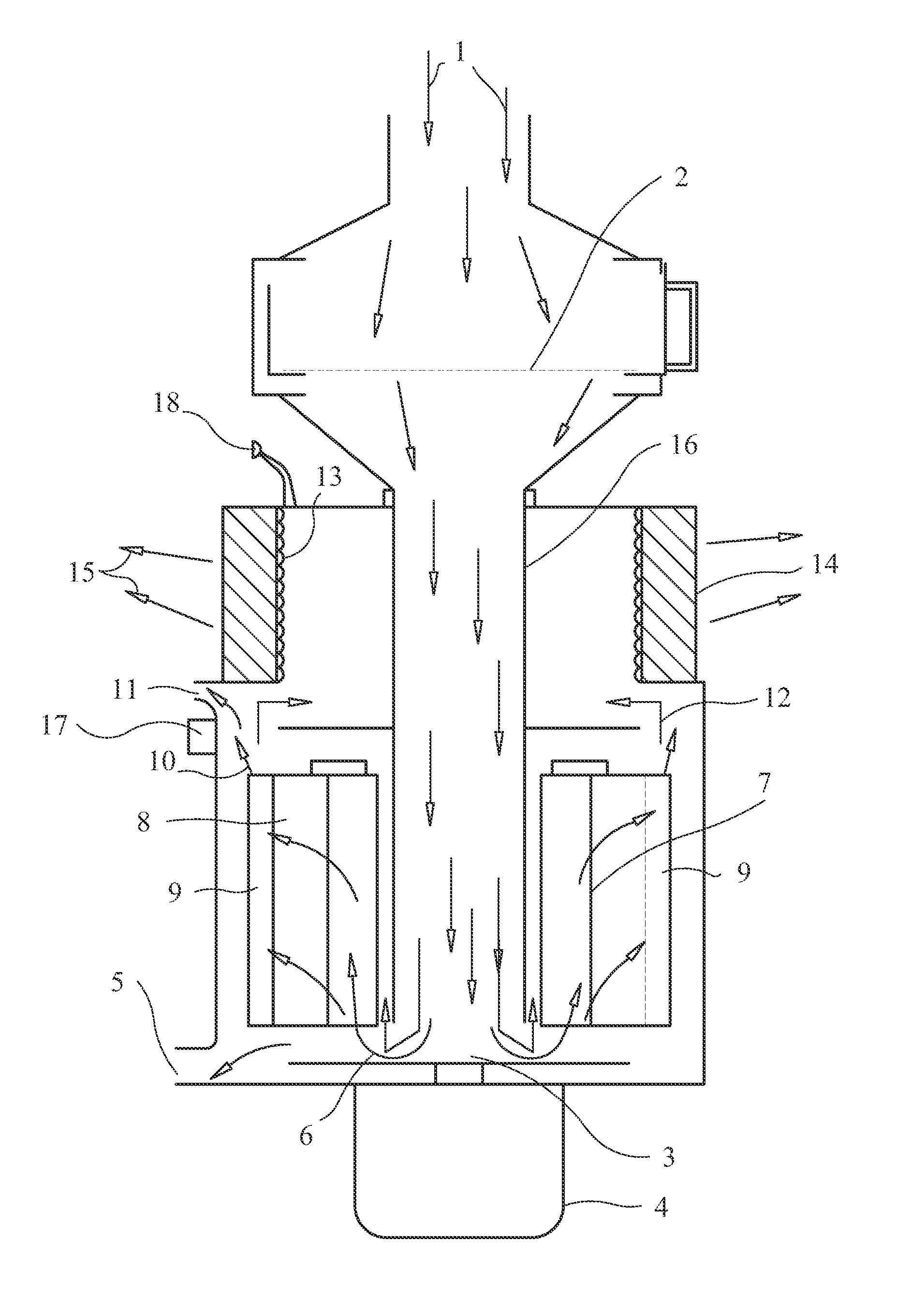
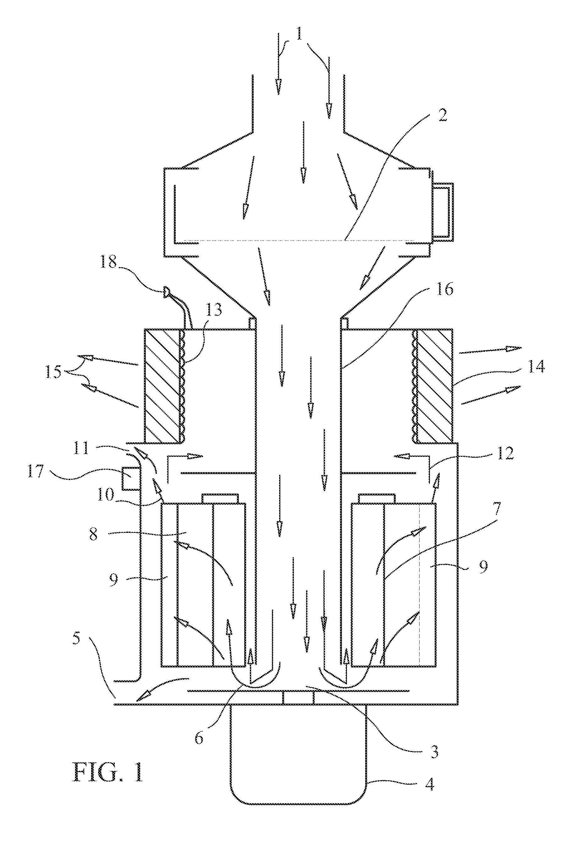
[0040]The vertical filtering and separating suction machine of chips, steam and smoke by change of air direction, for machining center, lathe machine or other machines generating steam from oil or coolant that is disclosed in this presentation, consists of the following parts, pieces or sections:

[0041]A pipe, preferably made of rigid plastic which serves as an air collector and which is connected to the sector of the machining center (or another cutting machine) where mist to be sucked is generated, about 110 mm. in diameter, and whose length and route will be modified according to the features of workplace, the place where the suction machine will be located and other variables.

[0042]A parallelepiped-shaped cabin, about 25 cm.×26 cm×11 cm. high, preferably made of galvanized sheet since it is lightweight, resistant and stainless, crossed transversely by a removable drawer of about 22 cm.×25 cm.×7 cm., whose bottom is composed of a thick metal mesh n°6 (i.e. with6 wires per inch) of...


PUM

PropertyMeasurementUnit
Angleaaaaaaaaaa
Angleaaaaaaaaaa
Currentaaaaaaaaaa

Abstract

The invention hereby disclosed is a vertical filtering and separating suction machine of chips, steam and smoke for machining center, lathe machine or other machines, which operates by sudden changes of sucked air, thus generating hits which separate heavy particles, whose suction pipe extends almost up to the bottom of the rotor, which only uses filters at the end of the process of air purification, whose rotor has outer paddles modified in order to improve suction power and to cause more hits of air flow, and which includes an air pressure alarm showing the filter is saturated.

Description

[0001]The present invention consists of a vertical filtering and separating suction machine of chips, steam and smoke, which operates primarily by sudden changes of direction in the air flows, specially adapted for machining centers, lathes and machines of the kind that while operating, produces light chips, oil steam or coolant steam, such as cutting machines, grinders, antirust applicators, which in order to prevent these pollutants from spreading throughout the plant environment, sucks and purifies the air inside the machine.[0002]Protection is given to a filtering and separating suction machine, of the kind that separates heavy elements by violent changes of direction of the air inside, by taking advantage of the different specific gravity of air in relation to its pollutants, and using vertical suction to increase the flow speed and improve efficiency in the separation process, with a lower energy expenditure, generating several flow hits, avoiding the use of primary filters in...

Claims


Application Information

Patent Timeline
IPC IPC(8): B23Q11/00B24B55/06B26D7/18
CPCB01D50/002B07B7/083B24B55/06B07B7/04B23Q11/0057B01D45/14B01D46/2403Y10T409/304088Y10T83/242B01D50/20
Inventor OTA, TOMIO
Owner OTA TOMIO
Why Eureka
Try Eureka