
Roller mill for comminuting brittle grinding stock

Active Publication Date: 2012-05-10
THYSSENKRUPP POLYSIUS AKTIENGES
View PDF1 Cites 21 Cited by
  • Summary
  • Abstract
  • Description
  • Claims
  • Application Information

AI Technical Summary

Benefits of technology

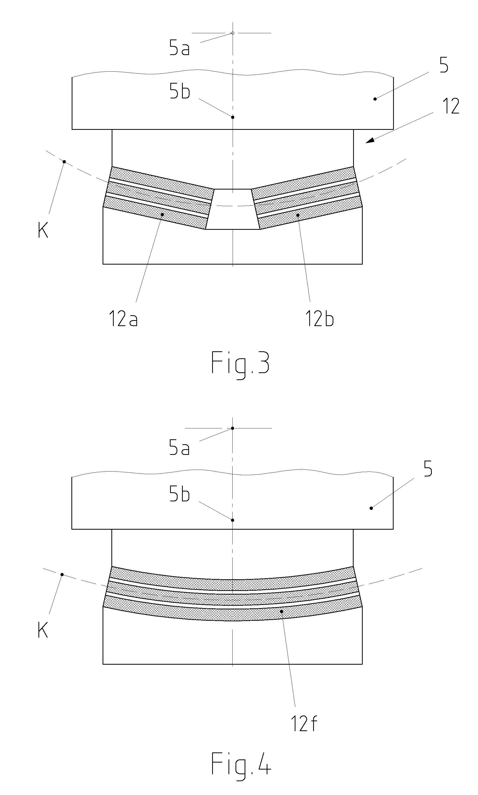
[0010]The tangential arrangement of at least two resilient compensation elements per bearing block or the circular arc construction of the compensation element enables the loads on the compensation element and the adjoining components during a rotary movement of the bearing blocks to be considerably reduced, whereby a greater operational reliability of the compensation elements and of the non-self-aligning bearings is achieved.
[0016]With these properties, the resilient compensation elements are distinguished by a high compressive strength and high yield to impact. This results in especially low restoring torques when the bearing blocks are skewed. In combination with the tangential arrangement or circular arc-shaped construction of the compensation elements this makes a positive contribution to a long service life of the compensation elements and the non-self-aligning bearings.

Problems solved by technology

In operation of these roll crushing mills, the axis of rotation of the loose roller may be subject to considerable skewing.
In the case of non-self-aligning types of bearing, this misalignment may lead to a distortion of the bearing housings of the loose roller in the machine frame.
In addition to the distortion of the bearing housings resulting from the skewed position of the axis of rotation of the loose roller, additional distortion occurs as a result of deflection of the two axes.
This deflection leads to a slight distortion of the bearing housings of the fixed roller as well.
The necessary sealing of the rubber body is subject to wear and tear, however, which may lead to failure of the system.
In addition, high restoring forces develop, which can lead to damage to the non-adjustable bearings.

Method used


Image

  • Roller mill for comminuting brittle grinding stock
  • Roller mill for comminuting brittle grinding stock
  • Roller mill for comminuting brittle grinding stock

Examples


Embodiment Construction

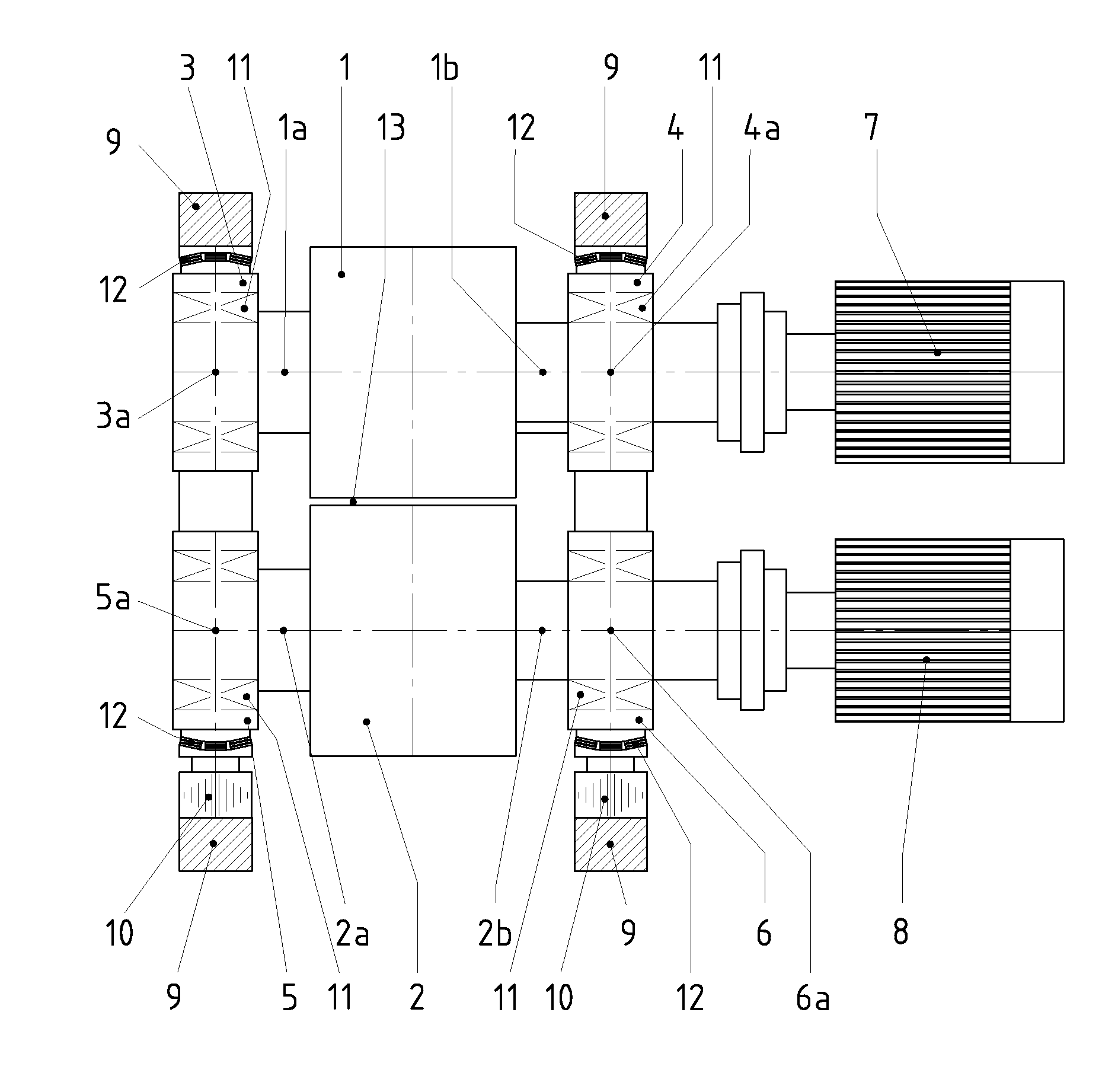
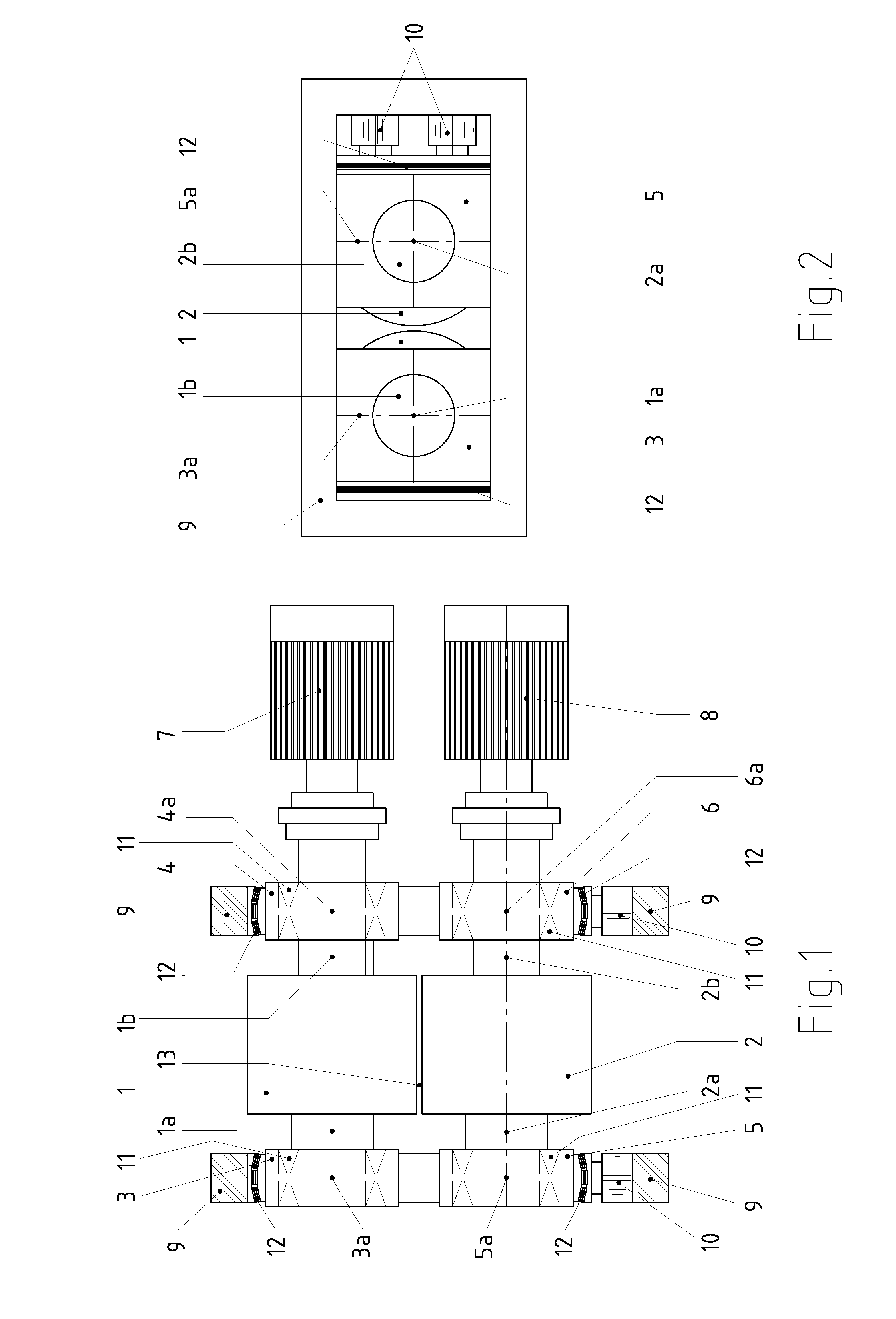
[0024]The exemplary embodiment according to FIGS. 1 and 2 shows a roller mill in the form of a roll crushing mill having a grinding roller 1 in the form of a loose roller and a grinding roller 2 in the form of a fixed roller, which are mounted so as to rotate with their grinding axes 1b and 2b, respectively, about axes of rotation 1a and 2a, respectively, in bearing blocks 3, 4 and 5, 6, respectively.

[0025]For that purpose, suitable bearings 11, such as, for example, cylindrical roller bearings, tapered roller bearings or sliding bearings, are mounted in the bearing blocks.

[0026]The bearing blocks 3 to 6 are horizontally slidable and are rotatably guided in a machine frame 8 about vertical bearing axes 3a, 4a, 5a and 6a, respectively, intersecting the axes of rotation 1a and 2a.

[0027]Furthermore, a pressing device 10 supported on the machine frame 9 is provided, in order to apply an adjustable grinding pressure to the grinding rollers via the bearing blocks 5, 6. In addition, at le...


PUM


Abstract

A roller mill for comminuting brittle grinding stock comprises at least one grinding roller constructed as a loose roller and rotatable about an axis and interacting with a counter-surface such that grinding stock is comminuted between the grinding roller and counter-surface. Horizontally slidable bearing blocks bear the grinding roller and are guided in a frame rotatably about a vertical bearing axis. A pressing device applies an adjustable grinding pressure to the grinding roller via the bearing blocks. At least two resilient compensation elements are associated with each bearing block in order to compensate a skewed position and / or deflection of the grinding roller. The compensation elements are arranged between the frame and the bearing blocks, and, in the plan view of the roller mill, are arranged tangentially to a circle around the vertical bearing axis or constructed in a circular arc around the vertical bearing axis.

Description

TECHNICAL FIELD[0001]The invention relates to a roller mill for comminuting brittle grinding stock.BACKGROUND OF THE INVENTION[0002]The roll crushing mill with two counter-driven grinding rollers pressed against each other is a roller mill frequently used in the comminution of brittle grinding stock. Here, one grinding roller is constructed with a pressing device (loose roller) and the other grinding roller is constructed without a pressing device (fixed roller) and both grinding rollers are mounted in horizontally slidable bearing blocks, wherein at least the loose roller is mounted in horizontally slidable bearing blocks and the bearing blocks are rotatably guided in the machine frame about a bearing axis vertically intersecting the axis of rotation.[0003]In a roll crushing mill with two counter-driven grinding rollers for comminuting brittle materials the two grinding rollers pressed against each other can be mounted in the bearing housing by non-self-aligning cylindrical roller ...

Claims


Application Information

Patent Timeline
IPC IPC(8): B02C4/32
CPCB02C4/02B02C4/32B02C4/28
Inventor RUTHER, THOMASPETERS, ALEXANDERKONNING, LUDWIGHORSTER, NILSGIESEMANN, REINHARD
Owner THYSSENKRUPP POLYSIUS AKTIENGES
Learn More