Power control system, power control method, power control device and power control program

a power control system and power control technology, applied in the direction of electrochemical generators, secondary cell servicing/maintenance, transportation and packaging, etc., can solve the problems of not systematically controlling the current based on the current used for charging the batteries, the inability to use the electric vehicle, and the likely thrown of the ampere breaker in the middle of the night, etc., to achieve the effect of efficient supply of power to an electric device and charging an electric vehicl

Inactive Publication Date: 2012-05-10
PANASONIC INTELLECTUAL PROPERTY MANAGEMENT CO LTD
View PDF6 Cites 102 Cited by
  • Summary
  • Abstract
  • Description
  • Claims
  • Application Information

AI Technical Summary

Benefits of technology

[0031]The present invention was contrived in order to solve the problems described above. An object of the present invention is to provide a power control system, a power control method, a power control device and a power control program, which can efficiently supply power to an electric device and charge an electric vehicle.
[0034]According to the present invention, because the power supply start time of supplying power to the electric device and the charging start time of charging the rechargeable battery are determined such that the supply of power to the electric device and the charging of the rechargeable battery are completed by the predetermined time prior to the arrival of the electric vehicle at the location where power is supplied to the electric vehicle, the supply of power to the electric device and the charging of the electric vehicle can be performed efficiently.

Problems solved by technology

Therefore, when the household equipment described above are operated intensively during the period between 11 p.m. and 7 a.m. producing the lowest electricity rate, the ampere breaker is likely to be thrown in the middle of the night.
If the user does not notice that the ampere breaker is off, in the morning the user not only sees the water not boiling or the rice not cooked in the programmed rice cooker, but also cannot use his / her electric vehicle because the rechargeable battery thereof is not charged.
However, not only general households but also business offices, factories and commercial facilities such as stores that use various electric devices and electric transporting vehicles have contract powers, which are the upper limits of electricity usages, and are demanding to use the electric device efficiently at low electricity rates within the range of the contract powers.
This on-board battery charger controls the current immediately before the contract power is exceeded, but does not systematically control the current based on the current used by the microwave and the current used for charging the batteries.
However, when using, at home, an electric water heater that needs continuous supply of power for a relatively long period of time and an electric car that needs to be charged for a relatively long period of time, a time period during which the power is supplied to the electric water heater should not overlap with a time period during which an on-board battery of the electric car is charged, so that these equipment do not compete over the electricity.
It is obvious that the best way is to end the boiling performed by the electric water heater and the charging of the on-board battery within the lowest electricity rate time slot, but this might cause a tremendous trouble when either one of the equipment needs to be used preferentially to reduce the amount of power consumed in the other.
In other words, what is expected is that the water in the electric water heater is not boiled when needed, and therefore hot water is not available, or that the battery of the electric car is not charged enough to be able to drive it to the destination.
However, when the electric car travels a significantly long distance and the remaining level of the on-board battery is extremely low, uncertain situations occur where a long charging time is required or larger current charging needs to be performed, making a power control operation extremely difficult.
Particularly, even when the on-board battery is charged after the electric water heater finishes boiling water, the charging might not be ended fully by the next morning.
In the conventional power control operation that combines the electric car and the microwave or other electric devices used for a short period of time, there is a problem that cannot be solved when combining an electric water heater and an electric car that uses large current for a long period of time.
Although the conventional methods are effective in this case, there remains a basic problem where the charging plan cannot be created until the electric vehicle is connected to the charger at home.
When the operation of the clothes washer / dryer is stopped until the electric vehicle is charged completely in order to prioritize charging of the electric vehicle, the clothes are immersed in detergent in the washer for several hours, which can damage the clothes.
However, when the charging takes too much time and the boiling does not end past 7 a.m., the hot water cannot be used for setting the table for breakfast.
In addition, there is a possibility that a large amount of power is supplied to the electric water heater after the lowest electricity rate time slot.
In the prior arts, therefore, the charging plan that prioritizes charging of the electric vehicle is created after the electric vehicle returns home, and thus cannot be coordinated with the operation of other electric devices, depending on when the electric vehicle returns home.

Method used


Image

  • Power control system, power control method, power control device and power control program
  • Power control system, power control method, power control device and power control program
  • Power control system, power control method, power control device and power control program

Examples


embodiment 1

Embodiment 1

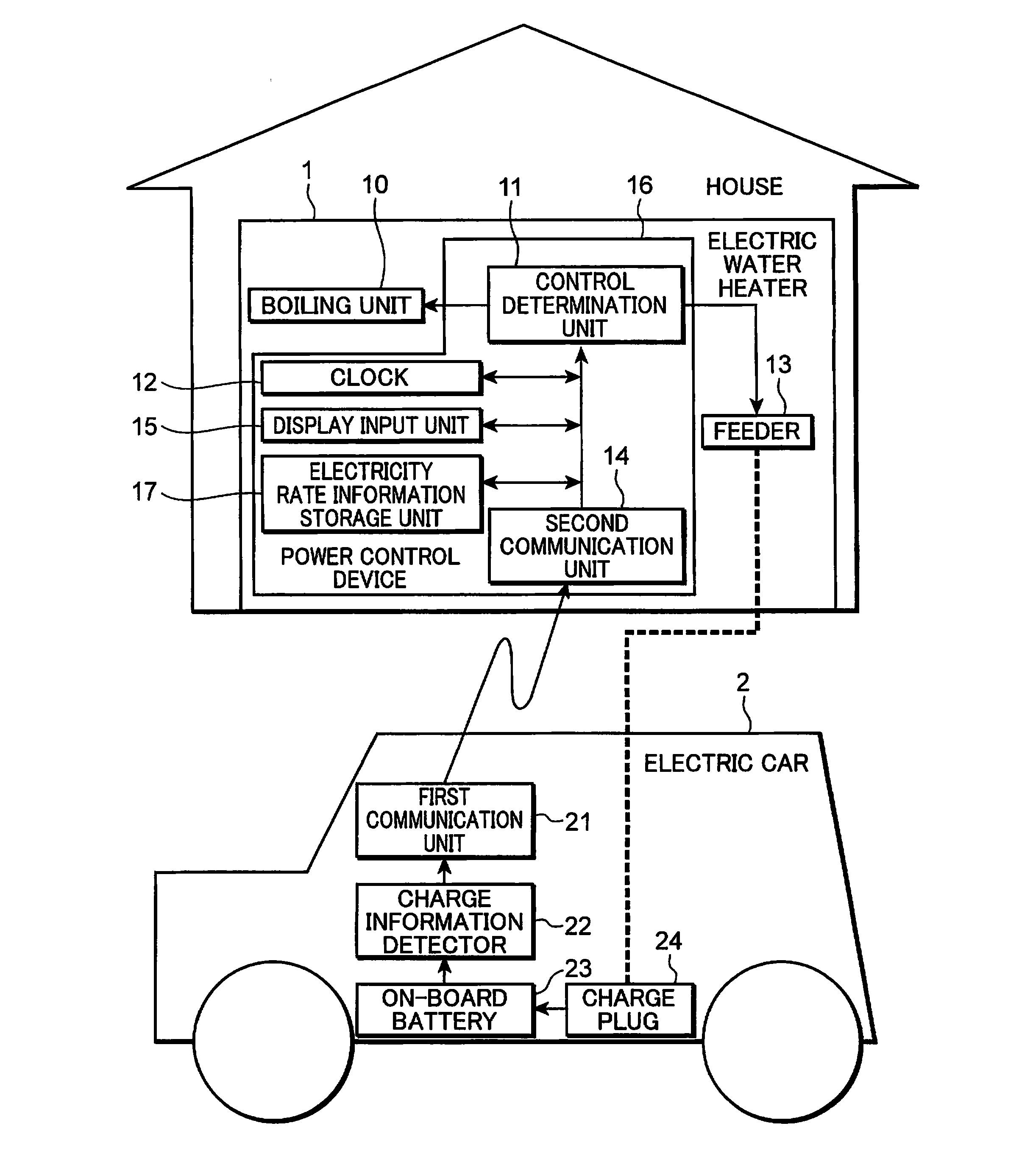
[0075]FIG. 1 is a diagram showing an example of a configuration of a power control system according to Embodiment 1 of the present invention. Embodiment 1 is described hereinafter with reference to FIG. 1.

[0076]The power control system shown in FIG. 1 has an electric water heater 1 and an electric car 2. The electric car 2 is an example of the electric vehicle, which is moved by receiving supply of power from a rechargeable battery equipped therein.

[0077]The electric car 2 is equipped with an on-board battery 23 for running a driving motor and an on-board electrical component, a charge plug 24, a charge information detector 22, and a first communication unit 21. The on-board battery 23 is charged by a feeder 13 (described later) via the charge plug 24. The charge information detector 22 acquires charge information pertaining to charging of a rechargeable battery. The charge information detector 22 detects charge information including a current remaining level of the on-...

embodiment 2

Embodiment 2

[0124]FIG. 7 is a diagram showing an example of a configuration of a power control system according to Embodiment 2 of the present invention. Embodiment 2 is described hereinafter with reference to FIG. 7.

[0125]The power control system shown in FIG. 7 has the electric water heater 1 and the electric car 2. The descriptions of the configurations according to Embodiment 2 that are the same as those of Embodiment 1 are omitted.

[0126]The electric car 2 is equipped with the on-board battery 23 for running a driving motor and an on-board electrical component, the charge plug 24, the charge information detector 22, the first communication unit 21, and an on-board navigation device 25. The on-board battery 23 is charged by the feeder 13 (described later) via the charge plug 24. The on-board navigation device 25 acquires information on a current position of the electric car 2 and provides information pertaining to a distance between the current position and the house. Note that ...

embodiment 3

Embodiment 3

[0169]The electric car 2 according to Embodiment 2 computes the remaining level of the on-board battery 23 that is obtained at the time of arrival of the electric car 2 at the installation location where the power control device 16 (the electric water heater 1) is installed. In Embodiment 3, on the other hand, a server device computes the remaining level of the on-board battery 23 that is obtained at the time of arrival of the electric car 2 at the installation location where the power control device 16 (the electric water heater 1) is installed.

[0170]FIG. 8 is a diagram showing an example of a configuration of a power control system according to Embodiment 3 of the present invention. Embodiment 3 is described with reference to FIG. 8.

[0171]The power control system shown in FIG. 8 has the electric water heater 1, the electric car 2, and a server device 3. The descriptions of the configurations according to Embodiment 3 that are the same as those of Embodiment 2 are omit...


PUM


Abstract

Disclosed are a power control system, a power control method, a power control device and a power control program, which can efficiently supply power to an electric device and charge an electric vehicle. A power control device (16) has: a second communication unit (14) that receives charge information pertaining to charging of an on-board battery (23) from an electric car (2) prior to the arrival of the electric car (2) at a location where power is supplied to the electric car (2); and a control determination unit (11) that determines a power supply start time of supplying power to an electric water heater (1) and a charging start time of charging the on-board battery (23), on the basis of the charge information, such that the supply of power to the electric water heater (1) and the charging of the on-board battery (23) are completed by a predetermined time.

Description

TECHNICAL FIELD[0001]The present invention relates to a power control system, a power control method, a power control device and a power control program for controlling charging of a rechargeable battery equipped in an electric vehicle and controlling supply of power to an electric device.BACKGROUND ART[0002]The use of a time-slot differentiated electricity rate system for leveling the power demanded of a power supplier can lower an electricity rate of a general household. For example, when the time-slot differentiated electricity rate system is used, the electricity rate is approximately 9 yen / kWh between 11 p.m. and 7 a.m., approximately 23 yen / kWh between 5 p.m. and 11 p.m. and between 7 a.m. and 10 a.m., and approximately 28 to 33 yen / kWh between 10 a.m. and 5 p.m.[0003]The lowest electricity rate between 11 p.m. and 7 a.m. is approximately ⅓ of the electricity rate obtained between 10 a.m. and 5 p.m. In the present specification, information pertaining to these power usage ti...

Claims


Application Information

Patent Timeline
Patent Type & Authority Applications(United States)
IPC IPC(8): H02J7/00H02J3/00H02J3/14H02J7/02
CPCB60L11/1816Y04S30/12B60L11/1846B60L11/1848B60L11/185B60L2240/622B60L2260/54Y02T10/7005Y02T90/121Y02T90/128Y02T90/14Y02T90/16Y02T90/162H01M10/44H01M10/48Y02T90/169Y04S30/14B60L11/184B60L2240/62B60L2240/70B60L2250/14B60L2260/50H02J2003/143H02J2003/146H02J3/14Y02T90/168Y02T10/7291B60L11/1838Y02T10/7072B60L53/14B60L53/64B60L53/63B60L53/65B60L53/665B60L53/11H02J2310/14H02J2310/64B60L53/66B60L53/68B60L53/62H02J2310/48H02J2310/12Y02T10/72Y02T10/70Y02T90/12Y02T90/167Y02E60/10
Inventor IKEDA, TOSHIHISAYOSHIMURA, YASUOTSUJIMURA, SATOSHINAKATANI, NAOFUMIKOUDA, TETSUYAKURIMOTO, KAZUNORI
Owner PANASONIC INTELLECTUAL PROPERTY MANAGEMENT CO LTD
Why Eureka
Try Eureka