Motor driven cabin air compressor with variable diffuser

a cabin air compressor and variable technology, applied in the direction of machines/engines, reaction engines, liquid fuel engines, etc., can solve the problem that the operation of dual air conditioning packs may not be necessary or efficien

Inactive Publication Date: 2012-05-10
HAMILTON SUNDSTRAND CORP
View PDF18 Cites 26 Cited by
  • Summary
  • Abstract
  • Description
  • Claims
  • Application Information

AI Technical Summary

Problems solved by technology

Unfortunately, operating dual air conditioning packs may not be necessary or efficient in some circumstances such as when the plane is on the tarmac.

Method used


Image

  • Motor driven cabin air compressor with variable diffuser
  • Motor driven cabin air compressor with variable diffuser
  • Motor driven cabin air compressor with variable diffuser

Examples


Embodiment Construction

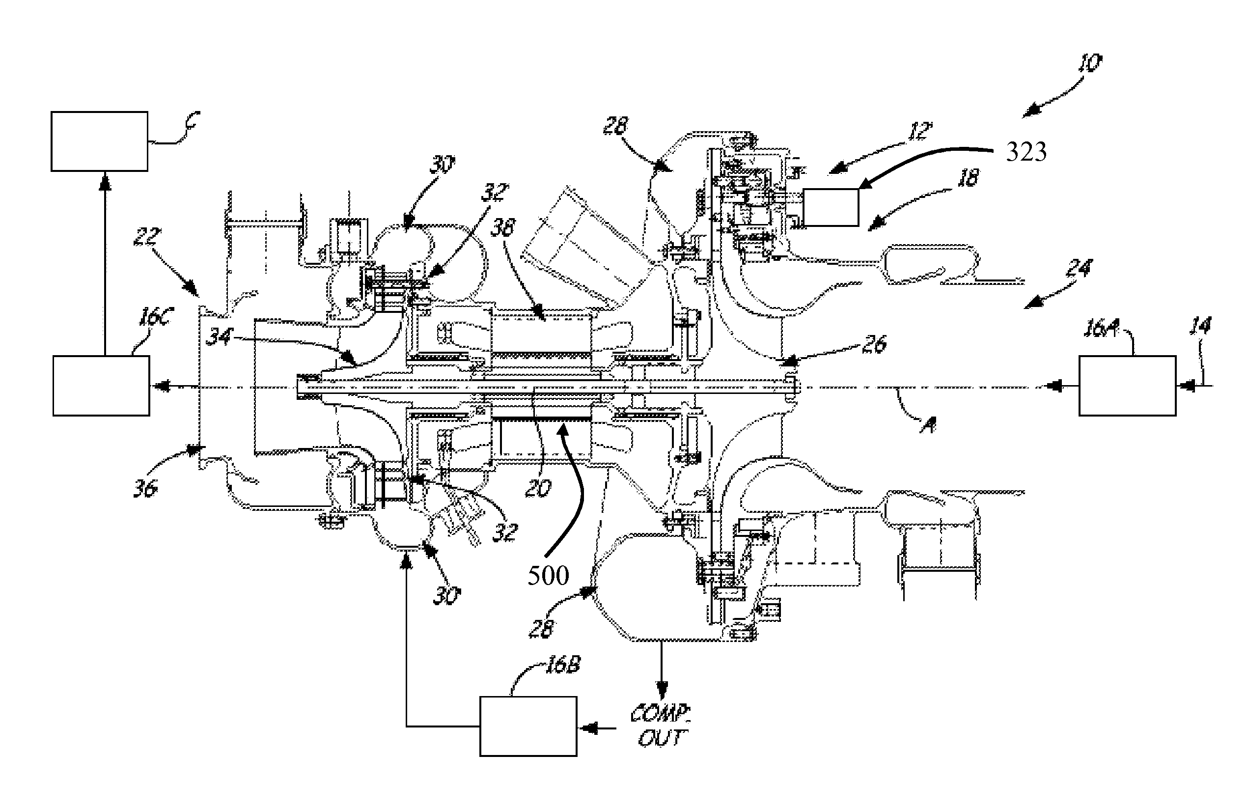
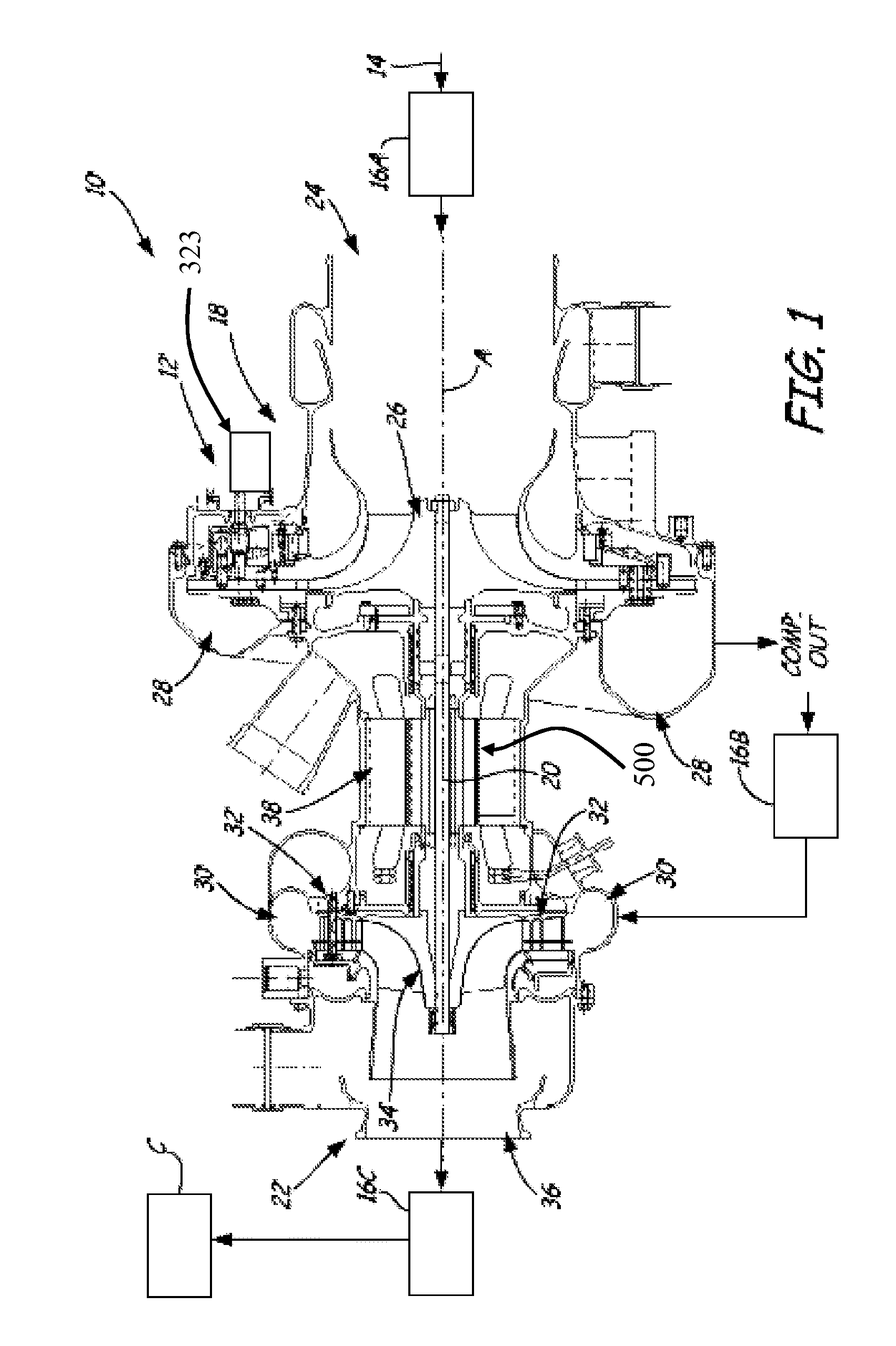
[0016]FIG. 1 shows a schematic view of an environmental control system (ECS) 10. The environmental control system 10 includes an air cycle machine 12 that receives air 14 that is conditioned by various devices symbolically indicated as 16A, 16B, and 16C to produce air flow at a desired temperature and pressure for aircraft cabin C. The air cycle machine 12 includes a compressor section 18, a shaft 20, and a turbine section 22. The compressor section 18 has a compressor inlet 24, a compressor wheel 26 and a compressor outlet 28. The turbine section 22 includes a turbine inlet 30, turbine inlet nozzle 32, turbine wheel 34 and turbine outlet 36.

[0017]System air 14 is bled from one or more of the compressor stages of the gas turbine engines of the aircraft or directed from an air source at another location on the aircraft. One or more devices 16A can condition (e.g., preheat, acoustically treat) the air 14 prior to its entry into the air cycle machine 12. The air 14 enters the air cycle...


PUM


Abstract

An air cycle machine is provided and includes a compressor section having a variable area diffuser, a turbine section having an inlet nozzle with a variable size, a motor to drive the compressor and a common rotating shaft on which the compressor section, the turbine section and the motor are mounted, the turbine section driving rotation of the shaft to drive the compressor section with the motor.

Description

BACKGROUND OF THE INVENTION[0001]The subject matter disclosed herein relates to a motor driven cabin air compressor with a variable diffuser.[0002]Aircraft environmental control systems incorporate turbomachines, commonly referred to as air cycle machines (ACMs), to help facilitate cooling and dehumidifying air for supply to a cabin of an aircraft. Air cycle machines can include two or more wheels having at least one compressor and at least one turbine disposed axially along the same shaft. On aircraft powered by gas turbine engines, the air to be conditioned in the air cycle machine is generally either compressed air bled from one or more of the compressor stages of the gas turbine engine or air diverted from another location on the aircraft. With either system, the air is passed through the compressor(s) of the air cycle machine where it is further compressed and then passed through a heat exchanger to cool the compressed air sufficiently to condense moisture therefrom. The dehumi...

Claims


Application Information

Patent Timeline
Patent Type & Authority Applications(United States)
IPC IPC(8): F04D29/46
CPCF04D29/462F04D25/0606
Inventor BEERS, CRAIG M.MCAULIFFE, CHRISTOPHER
Owner HAMILTON SUNDSTRAND CORP
Why Eureka
Try Eureka