Bone Fixation Device and Methods for Use Thereof

a bone fixation device and bone technology, applied in the field of medical devices, can solve problems such as patient injury, and achieve the effect of preventing damage to vital structures

Inactive Publication Date: 2012-05-10
NOTTMEIER ERIC W
View PDF4 Cites 39 Cited by
  • Summary
  • Abstract
  • Description
  • Claims
  • Application Information

AI Technical Summary

Benefits of technology

[0010]The present invention overcomes the aforementioned drawbacks by providing a bone fixation device that utilizes a self tapping screw and sharp guide rod that is interchangeable with a blunt-ended rod that is configured to prevent damage to vital structures. Such a device includes a self tapping screw having an aperture extending along a longitudinal axis of the screw, and a driver having an aperture extending from a proximal end to a distal end along a longitudinal axis of the driver, the distal end being configured to engage the screw such that the aperture of the driver and the aperture of the screw are coaxially aligned, thereby defining a lumen. Also included is a guide rod having a tapered tip for piercing bone tissue, the guide rod being shaped and dimensioned to extend through the lumen and configured to fasten to the driver, and a blunt-ended rod for advancing a bioactive agent through the lumen, the blunt-ended rod also being shaped and dimensioned to extend through the lumen.

Problems solved by technology

Precise placement of the K-wire is necessary, or nearby vital structures, such as the vertebral artery and spinal nerves, can be damaged, resulting in injury to the patient.

Method used


Image

  • Bone Fixation Device and Methods for Use Thereof
  • Bone Fixation Device and Methods for Use Thereof
  • Bone Fixation Device and Methods for Use Thereof

Examples


Embodiment Construction

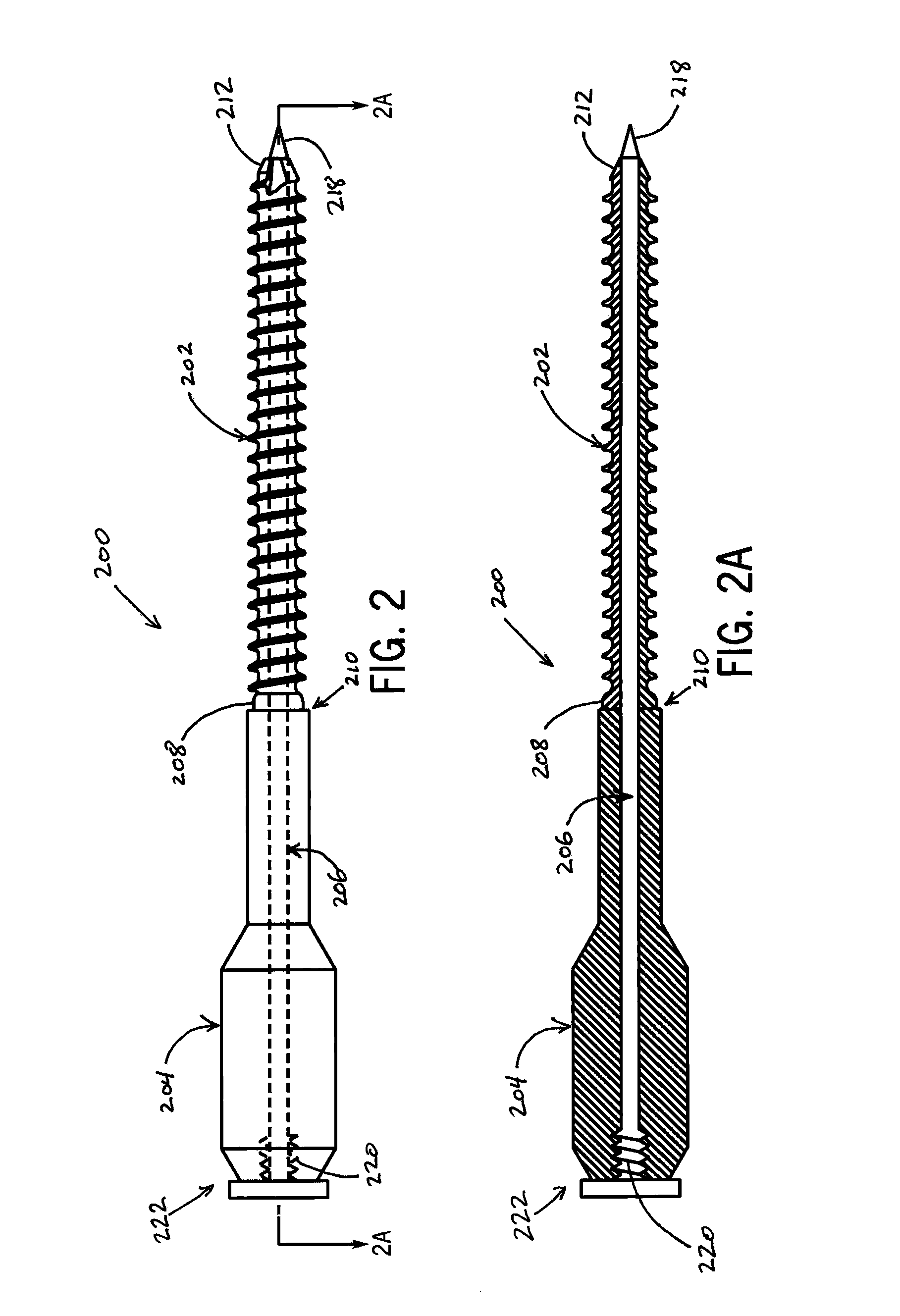
[0026]FIGS. 2, 2A, and 3 illustrate an exemplary bone fixation device 200 in accordance with the present invention. The bone fixation device 200 generally includes a cannulated screw 202, a cannulated driver 204, a guide rod 206, and a blunt-ended rod (not shown in FIGS. 2, 2A, and 3). As used herein, the term “cannulated” refers to an object having a hollow shaft, aperture, or lumen, running through it. Thus, a “cannulated screw” includes a screw having a hollow shaft, aperture, or lumen, running, for example, through the length of the screw. The cannulated screw 202, cannulated driver 204, guide rod 206, and blunt-ended rod are preferably composed of a material suitable for surgical use, such as stainless steel or titanium.

[0027]The head 208 of the cannulated screw 202 is configured to engage the distal end 210 of the cannulated driver 204, as illustrated in FIG. 4. The head 208 of the cannulated screw 202 may include any number of suitable drive types that allow for a centrally p...


PUM


Abstract

A bone fixation device for fixing a first bone to a second bone includes a self tapping screw having an aperture extending along a longitudinal axis of the screw, and a driver having an aperture extending from a proximal end to a distal end along a longitudinal axis of the driver, the distal end being configured to engage the screw such that the aperture of the driver and the aperture of the screw are coaxially aligned, thereby defining a lumen. A guide rod having a tapered tip for piercing bone tissue is shaped and dimensioned to extend through the lumen and configured to fasten to the driver. A blunt-ended rod advances a bioactive agent through the lumen, the blunt-ended rod being dimensioned to extend through the lumen to decrease the injury to vital structures as the screw is advanced into the second bone.

Description

CROSS-REFERENCES TO RELATED APPLICATIONS[0001]This application claims priority from U.S. Patent Application No. 61 / 409,426 filed Nov. 2, 2010.STATEMENT REGARDING FEDERALLY SPONSORED RESEARCH[0002]Not Applicable.BACKGROUND OF THE INVENTION[0003]1. Field of the Invention[0004]The field of the invention is medical devices and methods for their use. More particularly, the invention relates to medical devices for bone fixation and arthrodesis and methods for their use.[0005]2. Description of the Related Art[0006]Transarticular facet screw fixation is often used for treating instability between vertebrae, such as the atlas (C1 vertebra) and axis (C2 vertebra). This technique can also be used to fixate vertebrae inferior to the C2 vertebra and provides rigid internal fixation of the unstable vertebrae. In a typical C1-C2 fixation procedure, a midline incision is made on a patient from the occiput to the spinous process of, for example, the C5 vertebra, thereby exposing the C1 and C2 verteb...

Claims


Application Information

Patent Timeline
Patent Type & Authority Applications(United States)
IPC IPC(8): A61B17/86A61B17/88
CPCA61B17/7064A61B17/862A61B17/8635A61B2017/561A61B17/8883A61B17/8888A61B17/864
Inventor NOTTMEIER, ERIC W.
Owner NOTTMEIER ERIC W
Why Eureka
Try Eureka