Control system for plant

a control system and plant technology, applied in the field of plant control system, can solve the problems of difficult engine model, complex design of control system, and fear of interaction not being suppressed, and achieve the effect of easy design

Inactive Publication Date: 2012-05-10
HONDA MOTOR CO LTD
View PDF12 Cites 41 Cited by
  • Summary
  • Abstract
  • Description
  • Claims
  • Application Information

AI Technical Summary

Benefits of technology

[0007]It is an object of the present invention to provide a control system for a plant, which is capable of properly suppressing interaction occurring between a plurality of control inputs and a plurality of controlled variables, thereby making it possible to properly control the controlled variables, and can be easily designed.

Problems solved by technology

As described above, in the conventional control system, the system formed by combining the non-interacting controller and the engine is modeled as the linear imaginary plant with no interaction based on the non-interacting control law, but since the engine is a non-linear system, it is difficult to model the engine by the above-mentioned method.
Further, in a case where the conventional control system is applied to a plant with stronger non-linearity than that of the engine, the plant cannot be modeled, which causes a fear that the interaction cannot be suppressed.
This makes the design of the control system very complicated.

Method used


Image

  • Control system for plant
  • Control system for plant
  • Control system for plant

Examples


first embodiment

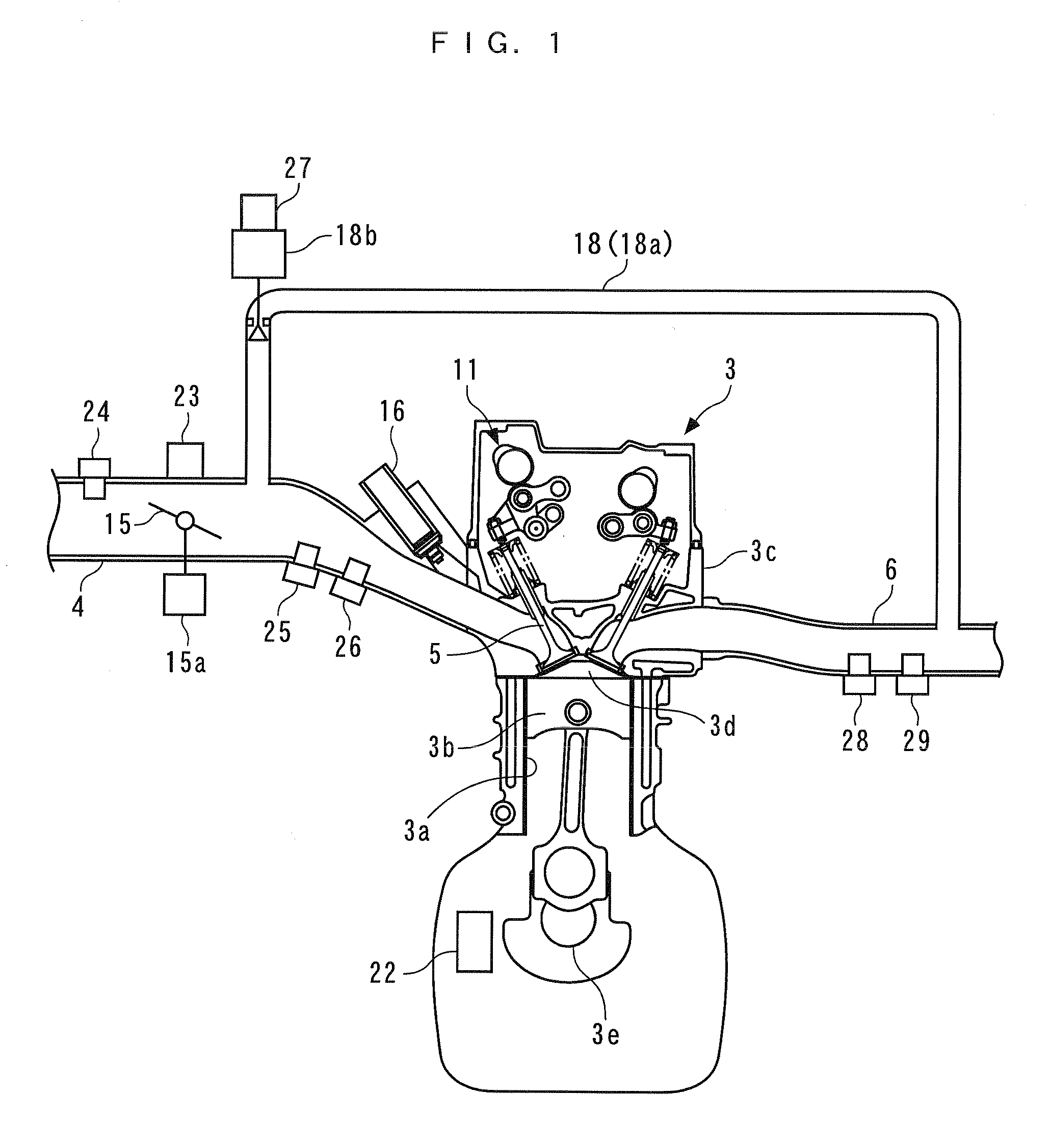
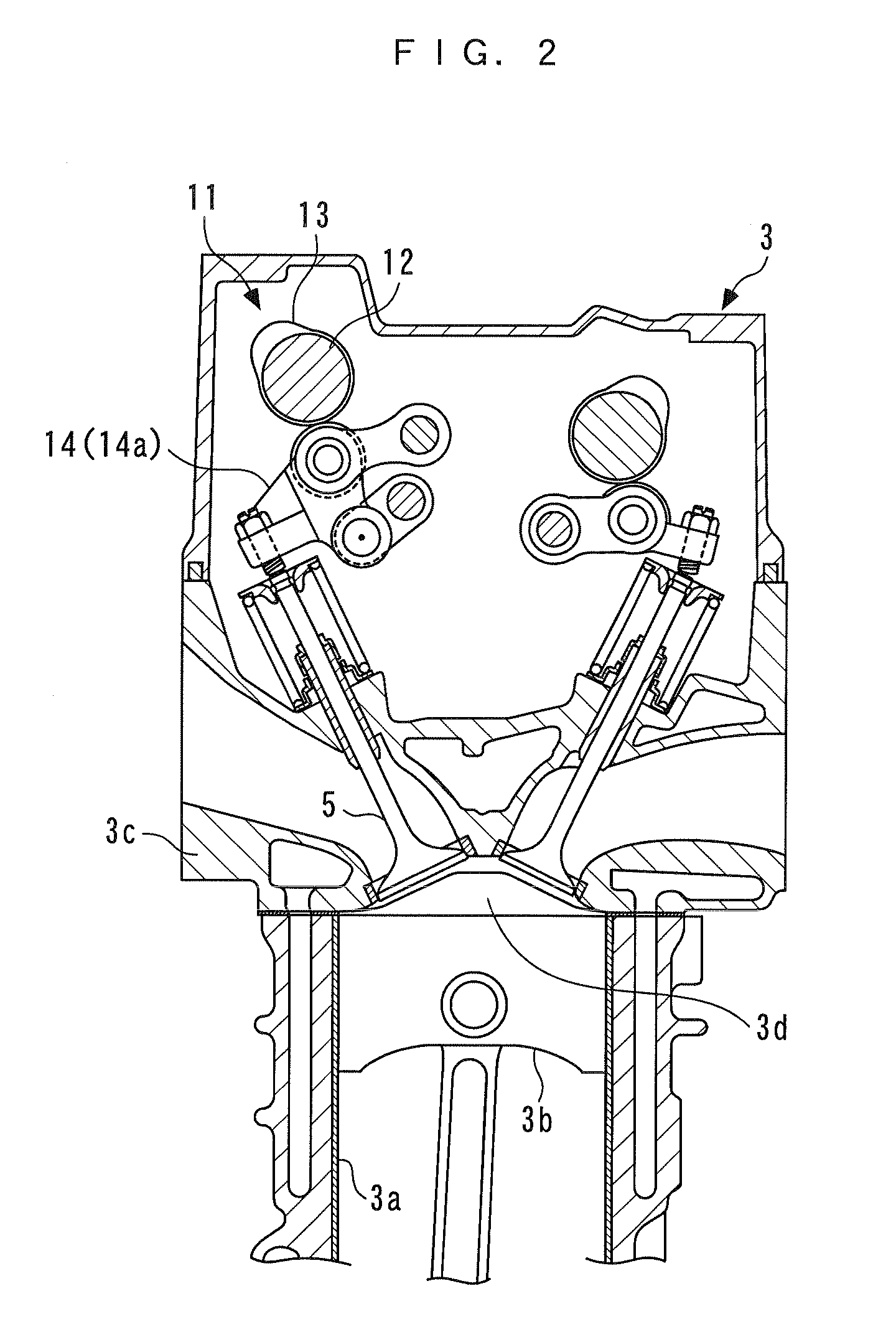
[0056]Hereafter, a control system according to the invention will be described in detail with reference to drawings. Referring to FIGS. 1 and 2, an internal combustion engine (hereinafter simply referred to as the “engine”) 3 is a gasoline engine installed on a vehicle, not shown, as a motive power source. The engine 3 is equipped with four cylinders 3a (only one of which is shown), an intake passage 4 for introducing intake air into the cylinders 3a, intake valves 5 (only one of which is shown) provided for the respective cylinders 3a, and an intake valve-actuating mechanism 11 for actuating the intake valves 5. Each cylinder 3a of the engine 3 has a combustion chamber 3d formed between a piston 3b in the cylinder 3a and a cylinder head 3c (only one of each of which is shown).

[0057]The above-mentioned intake passage 4 branches into four branch portions from the downstream side of an intake manifold thereof. The four branch portions are connected to the cylinder heads 3c, and commun...

second embodiment

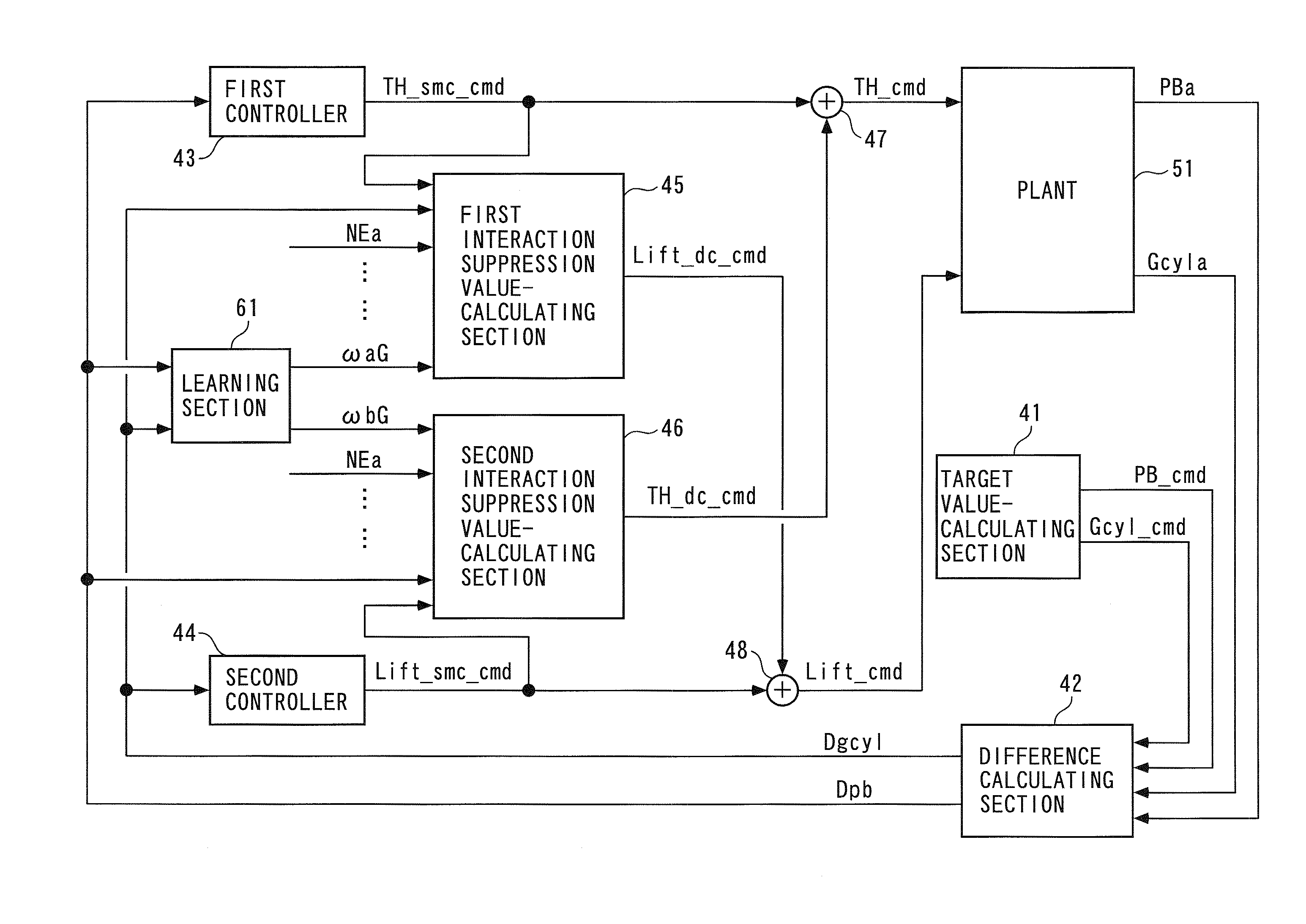
[0327]Further, the target low-pressure throttle valve opening LPTH_cmd and the target high-pressure throttle valve opening HPTH_cmd correspond to control inputs of the second invention, and the low-pressure EGR gas flow rate LPEGR and the high-pressure EGR gas flow rate HPEGR correspond to controlled variables of the second invention. Furthermore, the first and second interaction suppression value HPTH_dc_cmd and LPTH_dc_cmd correspond to interaction suppression parameters of the second invention, and the target low-pressure EGR gas flow rate LPEGR_cmd and the target high-pressure EGR gas flow rate HPEGR_cmd of the second embodiment correspond to target values of the second invention.

[0328]Further, the reward values Rw_hp and Rw_lp of the second embodiment correspond to rewards of the second invention, and the weighting factors ωc and ωd of the second embodiment correspond to neuron parameters of the second invention. The learning target high-pressure TH opening HPTH_cmdG and the le...


PUM


Abstract

A control system for a plant e.g. as a non-linear system, which is capable of properly suppressing interaction occurring between a plurality of control inputs and a plurality of controlled variables, thereby making it possible to properly control the controlled variables and easily design the control system. In the control system, each of a plurality of interaction suppression parameters for correcting the control inputs, respectively, such that the interaction is suppressed is calculated using a neural network constructed by using, out of the plurality of control inputs, a control input other than a control input corrected by a calculated interaction suppression parameter, as an input, and the interaction suppression parameter as an output.

Description

BACKGROUND OF THE INVENTION[0001]1. Field of the Invention[0002]The present invention relates to a control system for a plant in which a plurality of controlled variables are controlled by a plurality of control inputs, respectively, and interaction occurs between the control inputs and the controlled variables.[0003]2. Description of the Related Art[0004]Conventionally, as a control system of this kind, one disclosed in Japanese Laid-Open Patent Publication (Kokai) No. 2006-132429 is known. An internal combustion engine to which is applied this control system is configured such that the lift of intake valves can be changed. Further, in the conventional control system, a pressure within an intake passage (hereinafter referred to as the “intake pressure”) is controlled by controlling the degree of opening of a throttle valve disposed in the intake passage to a target opening thereof, and the amount of intake air drawn into the engine (hereinafter referred to as the “intake air amount...

Claims


Application Information

Patent Timeline
Patent Type & Authority Applications(United States)
IPC IPC(8): G06N3/08F02D28/00
CPCF02D13/0226G06N3/02F02D41/0002F02D41/0047F02D41/1405F02D2041/0017F02M25/0707F02M25/0709F02M25/0713F02M25/0718F02M25/0732F02M25/0756Y02T10/18G05B13/027F02D28/00F02M26/48F02M26/05F02M26/06F02M26/10F02M26/15F02M26/24Y02T10/12
Inventor HASHIMOTO, EIJIYASUI, YUJIHAGA, HISAONAKAJIMA, KOICHI
Owner HONDA MOTOR CO LTD
Why Eureka
Try Eureka